Brother International CB3-B917 Service Manual - Page 24
tooth counterclockwise from directly below and fit to
 |
View all Brother International CB3-B917 manuals
Add to My Manuals
Save this manual to your list of manuals |
Page 24 highlights
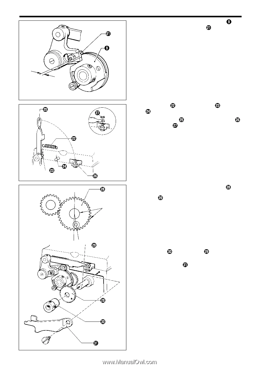
3. ASSEMBLY AND ADJUSTMENT 10. Tighten the number of stitches adjustment cam until the clearance between it and the pawl is 0.5 mm. 0.5 mm 312s 11. Attach the spring pin . to the spring hanger and dowel 12. Fit the connecting rod to the connecting rod shaft and attach the ring . 313s Apply grease 13. Move the number of stitches adjustment gear one tooth counterclockwise from directly below and fit to the drive shaft . 314s 14. Fit the set collar to the drive shaft , push gently, and tighten. 15. Attach the stitch 32 lever to the frame. 315s CB3-B916A/B917A 18
-
 1
1 -
2
-
3
-
4
-
5
-
6
-
7
-
8
-
9
-
10
-
11
-
12
-
13
-
14
-
15
-
16
-
17
-
18
-
 19
19 -
 20
20 -
 21
21 -
 22
22 -
 23
23 -
 24
24 -
 25
25 -
 26
26 -
 27
27 -
 28
28 -
 29
29 -
30
-
31
-
32
-
33
-
34
-
35
-
36
-
37
-
38
-
39
-
40
-
41
-
42
-
43
-
44
-
45
-
46
-
47
-
48
-
49
-
50
-
51
-
52
-
53
-
54
-
55
-
56
 |
 |
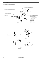
3. ASSEMBLY AND ADJUSTMENT
CB3-B916A/B917A
18
312s
0.5 mm
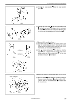
314s
Apply grease
315s
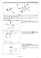
10. Tighten the number of stitches adjustment cam
until
the clearance between it and the pawl
is 0.5 mm.
11. Attach the spring
to the spring hanger
and dowel
pin
.
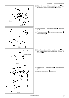
12. Fit the connecting rod
to the connecting rod shaft
and attach the ring
.
313s
13. Move the number of stitches adjustment gear
one
tooth counterclockwise from directly below and fit to the
drive shaft
.
14. Fit the set collar
to the drive shaft
, push gently, and
tighten.
15. Attach the stitch 32 lever
to the frame.