Brother International CB3-B917 Service Manual - Page 6
Contents
 |
View all Brother International CB3-B917 manuals
Add to My Manuals
Save this manual to your list of manuals |
Page 6 highlights
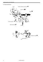
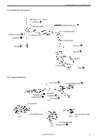
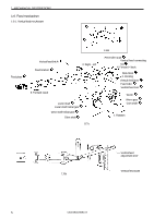
CONTENTS 1. MECHANICAL DESCRIPTIONS 1 1-1. Start mechanism 1 1-2. Number of stitches changing 2 1-3. Brake mechanism 3 1-4. Needle bar mechanism 4 1-5. Looper mechanism 4 1-6. Feed mechanism 5 1-7. Thread trimmer mechanism 7 1-8. Button clamp mechanism 8 1-9. Tension release mechanism 9 2. DISASSEMBLY 10 2-1. Cover 10 2-2. Clutch 10 2-3. Button clamp 11 2-4. Looper 12 2-5. Number of stitches changing 13 2-6. Needle bar 14 3. ASSEMBLY AND ADJUSTMENT----15 3-1. Needle bar 15 3-2. Number of stitches 17 3-3. Loopre 19 3-4. Button clamp 24 3-5. Clutch 25 3-6. Cover 26 4. REPLACEMENT OF PARTS------------28 4-1. Horizontal feed cam, vertical feed cam, worm gear, worm, number of stitches adjustment cam 28 4-2. Cushion rubber 33 4-3. Driving lever pawl 34 5. ADJUSTMENTS 35 5-1. Needle bar height 35 5-2. Loop spreader 35 5-3. Point where needle and looper meet 35 5-4. Clearance between needle bar and looper 35 5-5. Needle guard 35 5-6. Fixed knife 35 5-7. Movable knife 36 5-8. Stitch number 36 5-9. Number of stitches adjustment cam 36 5-10.Pawl of thread trimming lever 36 5-11.Button clamp driving lever 36 5-12.Worm and worm gear backlash 37 5-13.Pulley clearance in thrust direction 37 5-14.Slider 37 5-15.Auxiliary tension timing 38 5-16.Thread tension timing 38 5-17.Loop spreader timing 38 5-18.Forward and reverse feed 38 5-19.Button clamp installation 39 5-20.Elevation amount of button clamp 39 5-21.Feed timing 39 5-22.Clutch lever 39 5-23.Brake 39 5-24.Button clamp opener (B917A) 40 5-25.Thread take-up lever 40 5-26.Main tension 40 5-27.Rotor 41 5-28.Button clamp pressure 41 6. Troubleshooting 42
-
 1
1 -
 2
2 -
 3
3 -
 4
4 -
 5
5 -
 6
6 -
 7
7 -
 8
8 -
 9
9 -
 10
10 -
 11
11 -
 12
12 -
13
-
14
-
15
-
16
-
17
-
18
-
19
-
20
-
21
-
22
-
23
-
24
-
25
-
26
-
27
-
28
-
29
-
30
-
31
-
32
-
33
-
34
-
35
-
36
-
37
-
38
-
39
-
40
-
41
-
42
-
43
-
44
-
45
-
46
-
47
-
48
-
49
-
50
-
51
-
52
-
53
-
54
-
55
-
56
 |
 |