Brother International CB3-B917 Service Manual - Page 21
Assembly And Adjustment
 |
View all Brother International CB3-B917 manuals
Add to My Manuals
Save this manual to your list of manuals |
Page 21 highlights
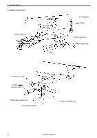
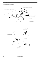
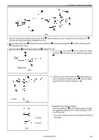
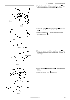
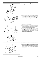
3. ASSEMBLY AND ADJUSTMENT 3. ASSEMBLY AND ADJUSTMENT CAUTION Assembly and adjustment of the sewing machine should only be carried out by a qualified technician. Turn off the power switch at the following times, otherwise the machine may operate if the pedal is depressed by mistake, which could result in injury. * The motor will keep turning even after the power is switched off as a result of the motor's inertia. Wait until the motor stops fully before starting work. • When carrying out inspection, adjustment and maintenance • When replacing consumable parts such as the loopers and knife. If the power switch needs to be left on when carrying out some adjustment, be extremely careful to observe all safety precautions. Be sure to wear protective goggles and gloves when handling the lubricating oil and grease, so that they do not get into your eyes or onto your skin, otherwise inflammation can result. Furthermore, do not drink the oil or eat the grease under any circumstances, as they can cause vomiting and diarrhoea. Keep the oil out of the reach of children. Use only the proper replacement parts as specified by Brother. If any safety devices have been removed, be absolutely sure to re-install them to their original positions and check that they operate correctly before using the machine. Any problems in machine operation which result from unauthorized modifications to the machine will not be covered by the warranty. 3-1. Needle bar Apply grease 1. The screw flat of the drive shaft lever should face up and be inserted through the needle bar drive lever and set collar . 2. Line up the end of the drive shaft lever with the frame and secure with the screw 301s Apply grease 3. Press the set collar gently to the needle bar drive lever and tighten the screw. *Make sure there is a washer put on part A of the needle bar drive lever . Push lightly A 302s Mark 4. Line up the mark at the upper part of the crank rod and attach. *While turning the stop cam (pulley), tighten the screw little by little so that torque will not be excessive. 303s Mark 15 CB3-B916A/B917A
-
 1
1 -
2
-
3
-
4
-
5
-
6
-
7
-
8
-
9
-
10
-
11
-
12
-
13
-
14
-
15
-
 16
16 -
 17
17 -
 18
18 -
 19
19 -
 20
20 -
 21
21 -
 22
22 -
 23
23 -
 24
24 -
 25
25 -
 26
26 -
27
-
28
-
29
-
30
-
31
-
32
-
33
-
34
-
35
-
36
-
37
-
38
-
39
-
40
-
41
-
42
-
43
-
44
-
45
-
46
-
47
-
48
-
49
-
50
-
51
-
52
-
53
-
54
-
55
-
56
 |
 |