Brother International CB3-B917 Service Manual - Page 45
Button clamp installation, 20.Elevation amount of button clamp, 21.Feed timing, 22.Clutch lever,
 |
View all Brother International CB3-B917 manuals
Add to My Manuals
Save this manual to your list of manuals |
Page 45 highlights
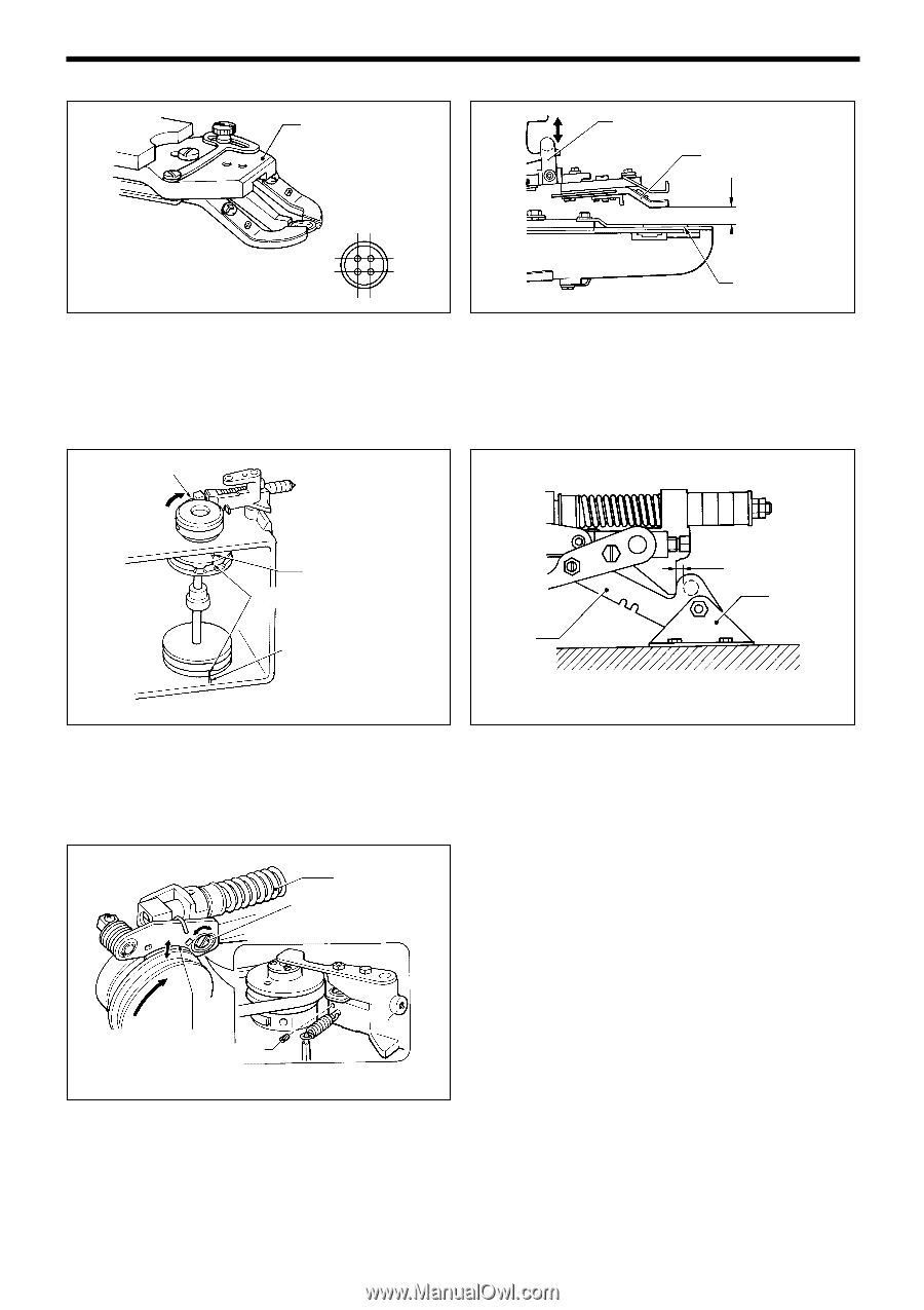
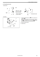
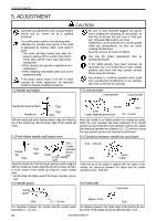
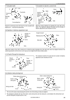
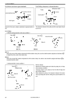
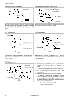
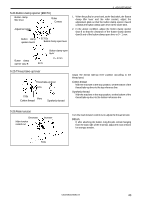
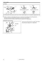
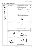
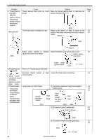
5. ADJUSTMENT 5-19.Button clamp installation Button clamp 5-20.Elevation amount of button clamp Button clamp regulating plate Button clamp 13 - 14 mm 513s 514s Feed plate Place the button on the button clamp and set the scale of the horizontal feed and the vertical feed to the distance between the buttons. The needle should be centered over the button holes. The distance between the upper part of the feed plate and the tip of the button clamp should be 13 - 14 mm. 5-21.Feed timing Contact 5-22.Clutch lever Cam positioning pin Mark Cam positioning pin Clutch lever 0.5 - 1 mm Clutch lever base 423s 515s Adjust the feed cam so that the index on the feed cam is Adjust the clutch lever base so there is a 0.5 to 1 mm gap aligned with the cam positioning pin when the machine is in between the clutch lever shaft and clutch when the machine is the stop position. in the stop position. 5-23.Braking force Brake shoe Set screw 516s Clutch body Brake lever shaft 1. While pushing the clutch body down, turn the machine pulley two or more complete turns in the direction of the arrow. 2. Loosen the set screw at the lower part of the clutch body. 3. Turn the brake lever shaft until the brake shoe is at its lowest position. 4. Tighten the set screw to secure the brake lever shaft. * If the brake is grabbing at low temperatures and low operating speeds and causing the machine to stop before the correct stopping position, it might be caused by one of the following problems. In such cases, raise the position of the brake shoe in step (3.) above. Work clamp lift amount is too small Thread is not being trimmed 39 CB3-B916A/B917A
-
 1
1 -
2
-
3
-
4
-
5
-
6
-
7
-
8
-
9
-
10
-
11
-
12
-
13
-
14
-
15
-
16
-
17
-
18
-
19
-
20
-
21
-
22
-
23
-
24
-
25
-
26
-
27
-
28
-
29
-
30
-
31
-
32
-
33
-
34
-
35
-
36
-
37
-
38
-
39
-
 40
40 -
 41
41 -
 42
42 -
 43
43 -
 44
44 -
 45
45 -
 46
46 -
 47
47 -
 48
48 -
 49
49 -
 50
50 -
51
-
52
-
53
-
54
-
55
-
56
 |
 |