Compaq Presario CQ41-200 Compaq Presario CQ41 Notebook PC - Maintenance and S - Page 59
Keyboard cover
 |
View all Compaq Presario CQ41-200 manuals
Add to My Manuals
Save this manual to your list of manuals |
Page 59 highlights
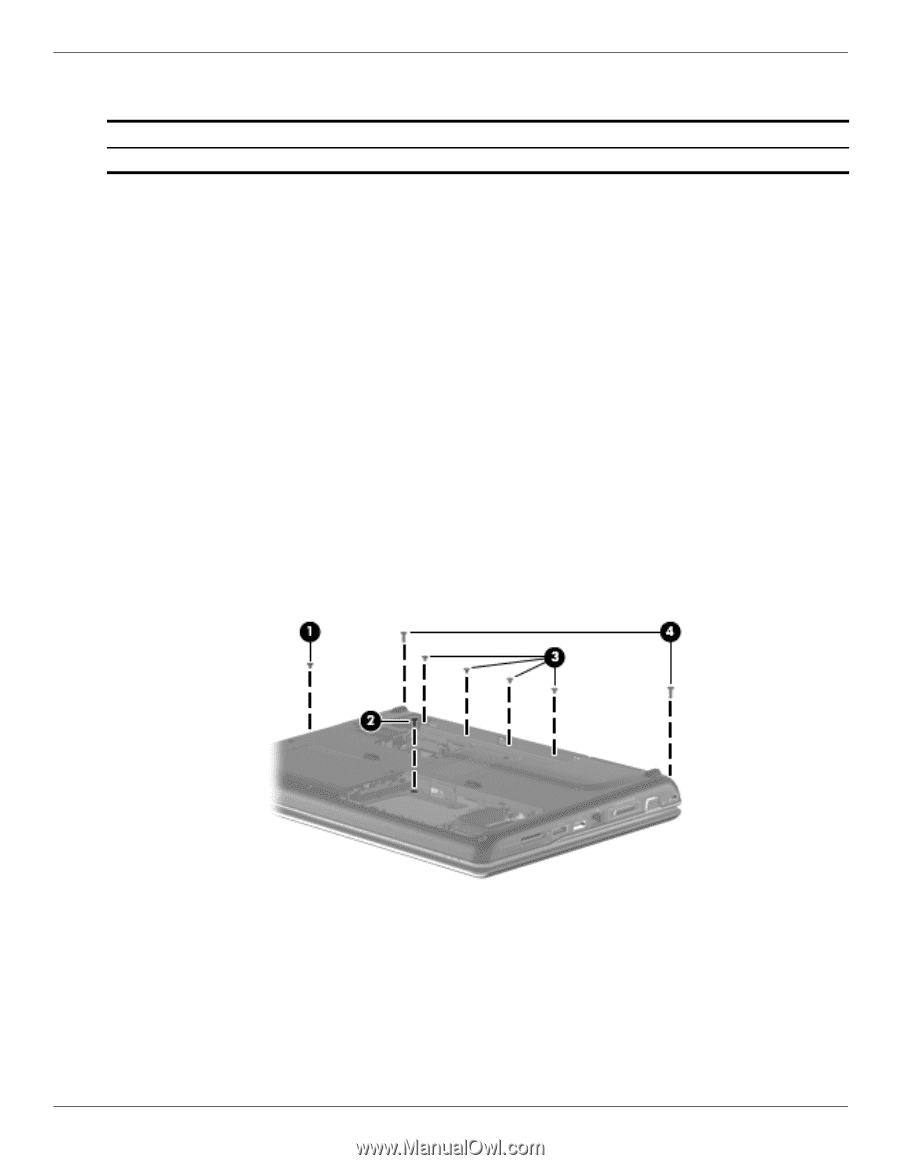
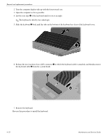
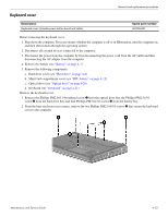
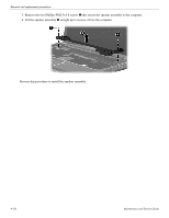
Keyboard cover Removal and replacement procedures Description Keyboard cover (includes power button board and cable) Spare part number 487299-001 Before removing the keyboard cover: 1. Shut down the computer. If you are unsure whether the computer is off or in Hibernation, turn the computer on, and then shut it down through the operating system. 2. Disconnect all external devices connected to the computer. 3. Disconnect the power from the computer by first disconnecting the power cord from the AC outlet and then disconnecting the AC adapter from the computer. 4. Remove the battery (see "Battery" on page 4-7). 5. Remove the following components: a. Hard drive cover (see "Hard drive" on page 4-8) b. Mini Card compartment cover (see "RTC battery" on page 4-12) c. Optical drive (see "Optical drive" on page 4-20) d. Keyboard (see "Keyboard" on page 4-21) Remove the keyboard cover: 1. Remove the Phillips PM2.0×3.0 broadhead screw 1 from the optical drive bay, the Phillips PM2.5×5.0 screw 2 from the hard drive bay, and four Phillips PM2.0×3.0 screws 3 from the battery bay. 2. From the base enclosure rear corners, remove the two Phillips PM2.5×10.0 screws 4 that secure the keyboard cover to the computer. Maintenance and Service Guide 4-23
-
 1
1 -
2
-
3
-
4
-
5
-
6
-
7
-
8
-
9
-
10
-
11
-
12
-
13
-
14
-
15
-
16
-
17
-
18
-
19
-
20
-
21
-
22
-
23
-
24
-
25
-
26
-
27
-
28
-
29
-
30
-
31
-
32
-
33
-
34
-
35
-
36
-
37
-
38
-
39
-
40
-
41
-
42
-
43
-
44
-
45
-
46
-
47
-
48
-
49
-
50
-
51
-
52
-
53
-
 54
54 -
 55
55 -
 56
56 -
 57
57 -
 58
58 -
 59
59 -
 60
60 -
 61
61 -
 62
62 -
 63
63 -
 64
64 -
65
-
66
-
67
-
68
-
69
-
70
-
71
-
72
-
73
-
74
-
75
-
76
-
77
-
78
-
79
-
80
-
81
-
82
-
83
-
84
-
85
-
86
-
87
-
88
-
89
-
90
-
91
-
92
-
93
-
94
-
95
-
96
-
97
-
98
-
99
-
100
-
101
-
102
-
103
-
104
-
105
-
106
-
107
-
108
-
109
-
110
-
111
-
112
-
113
-
114
-
115
-
116
-
117
-
118
-
119
-
120
-
121
-
122
-
123
-
124
-
125
-
126
-
127
-
128
-
129
-
130
-
131
-
132
-
133
-
134
 |
 |