Compaq Presario CQ41-200 Compaq Presario CQ41 Notebook PC - Maintenance and S - Page 68
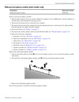
Remove the wireless antenna transceivers and cables, built into the display enclosure.
 |
View all Compaq Presario CQ41-200 manuals
Add to My Manuals
Save this manual to your list of manuals |
Page 68 highlights
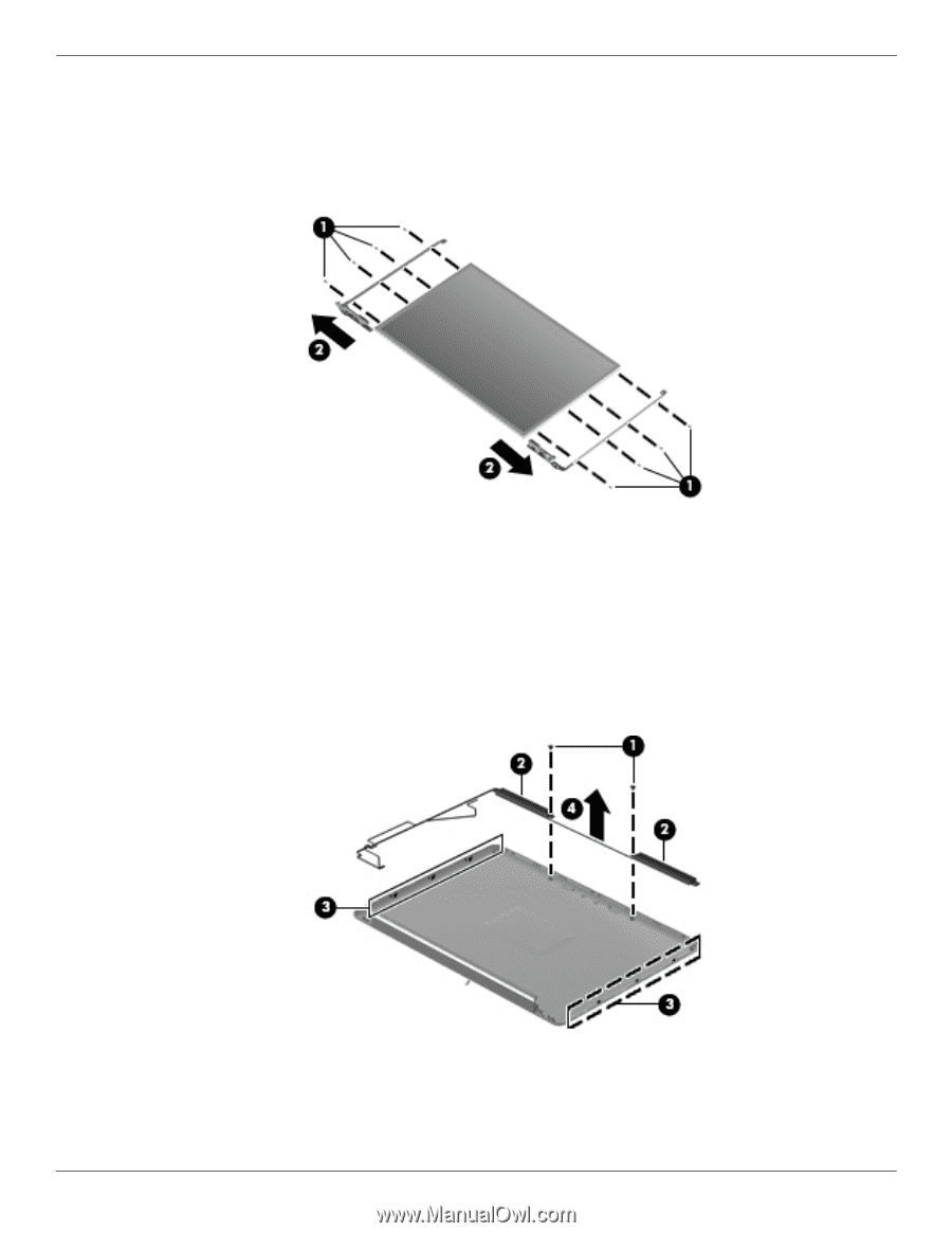
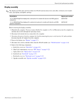
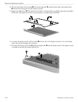
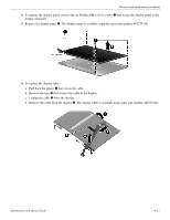
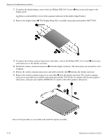
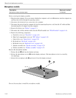
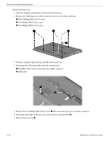
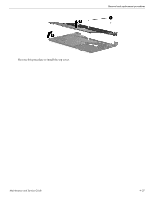
Removal and replacement procedures 17. To replace the display hinges, remove the four Phillips PM2.0×3.0 screws 1 that secure each hinge to the display panel. ✎ Remove and install the screws in the sequence indicated on the display hinge bracket. 18. Remove the display hinges 2. The Display Hinge Kit is available using spare part number 486737-001. 19. To replace the wireless antenna transceivers and cables, remove the Phillips PM2.5×3.0 screw 1 that secures each transceiver to the display enclosure. 20. Detach the wireless antenna transceivers 2 from the display enclosure. The transceivers are secured by a foil wrapping. 21. Release the wireless antenna transceivers and cables from the clips 3 built into the display enclosure. 22. Remove the wireless antenna transceivers and cables 4 from the display enclosure. The wireless antenna transceivers and cables are available using spare part number 502979-001 for models with discrete graphics subsystems, and spare part number 489066-001 for models with UMA graphics subsystems. Reverse this procedure to reassemble and install the display assembly. 4-32 Maintenance and Service Guide
-
 1
1 -
2
-
3
-
4
-
5
-
6
-
7
-
8
-
9
-
10
-
11
-
12
-
13
-
14
-
15
-
16
-
17
-
18
-
19
-
20
-
21
-
22
-
23
-
24
-
25
-
26
-
27
-
28
-
29
-
30
-
31
-
32
-
33
-
34
-
35
-
36
-
37
-
38
-
39
-
40
-
41
-
42
-
43
-
44
-
45
-
46
-
47
-
48
-
49
-
50
-
51
-
52
-
53
-
54
-
55
-
56
-
57
-
58
-
59
-
60
-
61
-
62
-
 63
63 -
 64
64 -
 65
65 -
 66
66 -
 67
67 -
 68
68 -
 69
69 -
 70
70 -
 71
71 -
 72
72 -
 73
73 -
74
-
75
-
76
-
77
-
78
-
79
-
80
-
81
-
82
-
83
-
84
-
85
-
86
-
87
-
88
-
89
-
90
-
91
-
92
-
93
-
94
-
95
-
96
-
97
-
98
-
99
-
100
-
101
-
102
-
103
-
104
-
105
-
106
-
107
-
108
-
109
-
110
-
111
-
112
-
113
-
114
-
115
-
116
-
117
-
118
-
119
-
120
-
121
-
122
-
123
-
124
-
125
-
126
-
127
-
128
-
129
-
130
-
131
-
132
-
133
-
134
 |
 |