Compaq Presario CQ41-200 Compaq Presario CQ41 Notebook PC - Maintenance and S - Page 89
Remove the fan/heat sink assembly, system board.
 |
View all Compaq Presario CQ41-200 manuals
Add to My Manuals
Save this manual to your list of manuals |
Page 89 highlights
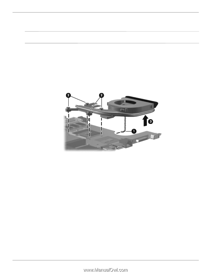
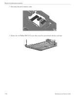
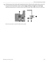
Removal and replacement procedures Remove the fan/heat sink: 1. Turn the system board upside down, with the front toward you. ✎ Steps two through four apply to computer models equipped with graphics subsystems with discrete memory. Steps five and six apply to computer models equipped with graphics subsystems with UMA memory. 2. Disconnect the fan cable 1. 3. Loosen the four captive Phillips PM2.0×10.0 screws 2 that secure the fan/heat sink assembly to the system board. 4. Remove the fan/heat sink assembly 3. ✎ Due to the adhesive quality of the thermal material located between the fan/heat sink assembly and system board components, it might be necessary to move the fan/heat sink assembly from side to side to detach the assembly. Maintenance and Service Guide 4-53
-
 1
1 -
2
-
3
-
4
-
5
-
6
-
7
-
8
-
9
-
10
-
11
-
12
-
13
-
14
-
15
-
16
-
17
-
18
-
19
-
20
-
21
-
22
-
23
-
24
-
25
-
26
-
27
-
28
-
29
-
30
-
31
-
32
-
33
-
34
-
35
-
36
-
37
-
38
-
39
-
40
-
41
-
42
-
43
-
44
-
45
-
46
-
47
-
48
-
49
-
50
-
51
-
52
-
53
-
54
-
55
-
56
-
57
-
58
-
59
-
60
-
61
-
62
-
63
-
64
-
65
-
66
-
67
-
68
-
69
-
70
-
71
-
72
-
73
-
74
-
75
-
76
-
77
-
78
-
79
-
80
-
81
-
82
-
83
-
 84
84 -
 85
85 -
 86
86 -
 87
87 -
 88
88 -
 89
89 -
 90
90 -
 91
91 -
 92
92 -
 93
93 -
 94
94 -
95
-
96
-
97
-
98
-
99
-
100
-
101
-
102
-
103
-
104
-
105
-
106
-
107
-
108
-
109
-
110
-
111
-
112
-
113
-
114
-
115
-
116
-
117
-
118
-
119
-
120
-
121
-
122
-
123
-
124
-
125
-
126
-
127
-
128
-
129
-
130
-
131
-
132
-
133
-
134
 |
 |