Compaq Presario CQ41-200 Compaq Presario CQ41 Notebook PC - Maintenance and S - Page 63
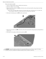
Display assembly, Disconnect the wireless antenna cables from the WLAN module see
 |
View all Compaq Presario CQ41-200 manuals
Add to My Manuals
Save this manual to your list of manuals |
Page 63 highlights
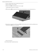
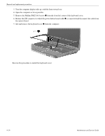
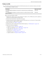
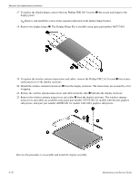
Removal and replacement procedures Display assembly ✎ The display assembly spare part kit includes two WLAN antenna transceivers and cables, webcam (select models only), microphone, nameplate, and logo. Description 14.1-in WXGA BrightView display with a microphone for models with discrete and UMA graphics subsystems 14.1-in WXGA BrightView display with a webcam/microphone for models with discrete and UMA graphics subsystems Spare part number 580763-001 580766-001 Before removing the display assembly: 1. Shut down the computer. If you are unsure whether the computer is off or in Hibernation, turn the computer on, and then shut it down through the operating system. 2. Disconnect all external devices connected to the computer. 3. Disconnect the power from the computer by first disconnecting the power cord from the AC outlet and then disconnecting the AC adapter from the computer. 4. Remove the battery (see "Battery" on page 4-7). 5. Disconnect the wireless antenna cables from the WLAN module (see "WLAN module" on page 4-14). 6. Remove the following components: a. Hard drive cover (see "Hard drive" on page 4-8) b. Mini Card compartment cover (see "RTC battery" on page 4-12) c. Optical drive (see "Optical drive" on page 4-20 d. Keyboard (see "Keyboard" on page 4-21) e. Keyboard cover (see "Keyboard cover" on page 4-23) f. Speaker assembly (see "Speaker assembly" on page 4-25) Maintenance and Service Guide 4-27
-
 1
1 -
2
-
3
-
4
-
5
-
6
-
7
-
8
-
9
-
10
-
11
-
12
-
13
-
14
-
15
-
16
-
17
-
18
-
19
-
20
-
21
-
22
-
23
-
24
-
25
-
26
-
27
-
28
-
29
-
30
-
31
-
32
-
33
-
34
-
35
-
36
-
37
-
38
-
39
-
40
-
41
-
42
-
43
-
44
-
45
-
46
-
47
-
48
-
49
-
50
-
51
-
52
-
53
-
54
-
55
-
56
-
57
-
 58
58 -
 59
59 -
 60
60 -
 61
61 -
 62
62 -
 63
63 -
 64
64 -
 65
65 -
 66
66 -
 67
67 -
 68
68 -
69
-
70
-
71
-
72
-
73
-
74
-
75
-
76
-
77
-
78
-
79
-
80
-
81
-
82
-
83
-
84
-
85
-
86
-
87
-
88
-
89
-
90
-
91
-
92
-
93
-
94
-
95
-
96
-
97
-
98
-
99
-
100
-
101
-
102
-
103
-
104
-
105
-
106
-
107
-
108
-
109
-
110
-
111
-
112
-
113
-
114
-
115
-
116
-
117
-
118
-
119
-
120
-
121
-
122
-
123
-
124
-
125
-
126
-
127
-
128
-
129
-
130
-
131
-
132
-
133
-
134
 |
 |