Compaq Presario CQ41-200 Compaq Presario CQ41 Notebook PC - Maintenance and S - Page 64
from the system board.
 |
View all Compaq Presario CQ41-200 manuals
Add to My Manuals
Save this manual to your list of manuals |
Page 64 highlights
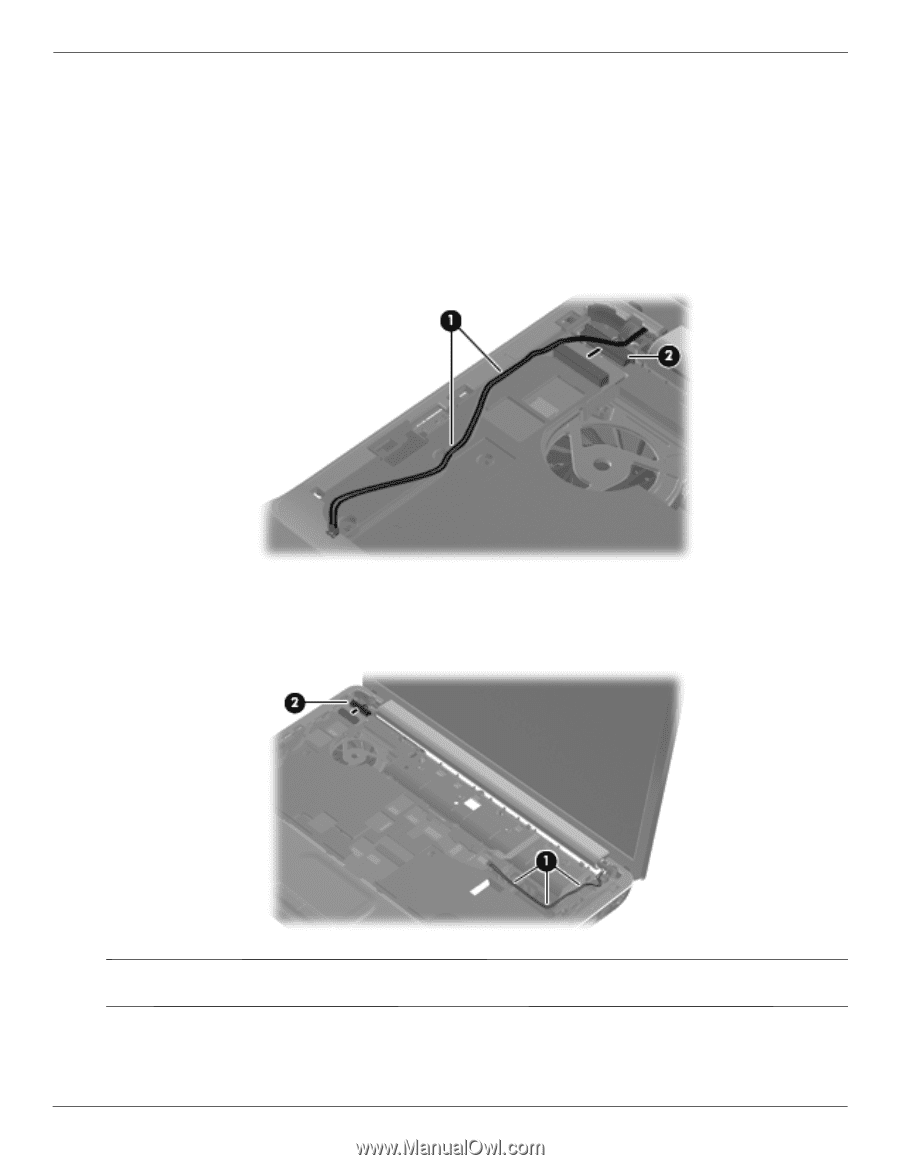
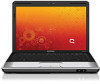
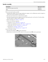
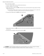
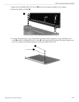
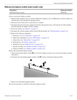
Removal and replacement procedures Remove the display assembly: 1. Turn the computer display-side up, with the front toward you. 2. Open the computer as far as possible. 3. Remove the wireless antenna cable 1 from the hole in the system board and the routing channels and clips built into the top cover. ✎ For models with UMA graphics subsystems, the antenna cable routes to the hard drive bay. For models with discrete graphics subsystems, the antenna cable routes to the Mini Card compartment. 4. Disconnect the display panel cable 2 from the system board. 5. Remove the microphone cable 1 from the hole in the system board and the routing channels and clips built into the top cover. 6. Disconnect the microphone cable from the system board 2. Ä CAUTION: Support the display assembly when removing the following screws. Failure to support the display assembly can result in damage to the display assembly and other computer components. 4-28 Maintenance and Service Guide
-
 1
1 -
2
-
3
-
4
-
5
-
6
-
7
-
8
-
9
-
10
-
11
-
12
-
13
-
14
-
15
-
16
-
17
-
18
-
19
-
20
-
21
-
22
-
23
-
24
-
25
-
26
-
27
-
28
-
29
-
30
-
31
-
32
-
33
-
34
-
35
-
36
-
37
-
38
-
39
-
40
-
41
-
42
-
43
-
44
-
45
-
46
-
47
-
48
-
49
-
50
-
51
-
52
-
53
-
54
-
55
-
56
-
57
-
58
-
 59
59 -
 60
60 -
 61
61 -
 62
62 -
 63
63 -
 64
64 -
 65
65 -
 66
66 -
 67
67 -
 68
68 -
 69
69 -
70
-
71
-
72
-
73
-
74
-
75
-
76
-
77
-
78
-
79
-
80
-
81
-
82
-
83
-
84
-
85
-
86
-
87
-
88
-
89
-
90
-
91
-
92
-
93
-
94
-
95
-
96
-
97
-
98
-
99
-
100
-
101
-
102
-
103
-
104
-
105
-
106
-
107
-
108
-
109
-
110
-
111
-
112
-
113
-
114
-
115
-
116
-
117
-
118
-
119
-
120
-
121
-
122
-
123
-
124
-
125
-
126
-
127
-
128
-
129
-
130
-
131
-
132
-
133
-
134
 |
 |