Compaq Presario CQ41-200 Compaq Presario CQ41 Notebook PC - Maintenance and S - Page 92
Fan (for models with UMA graphics subsystems), Display assembly see
 |
View all Compaq Presario CQ41-200 manuals
Add to My Manuals
Save this manual to your list of manuals |
Page 92 highlights
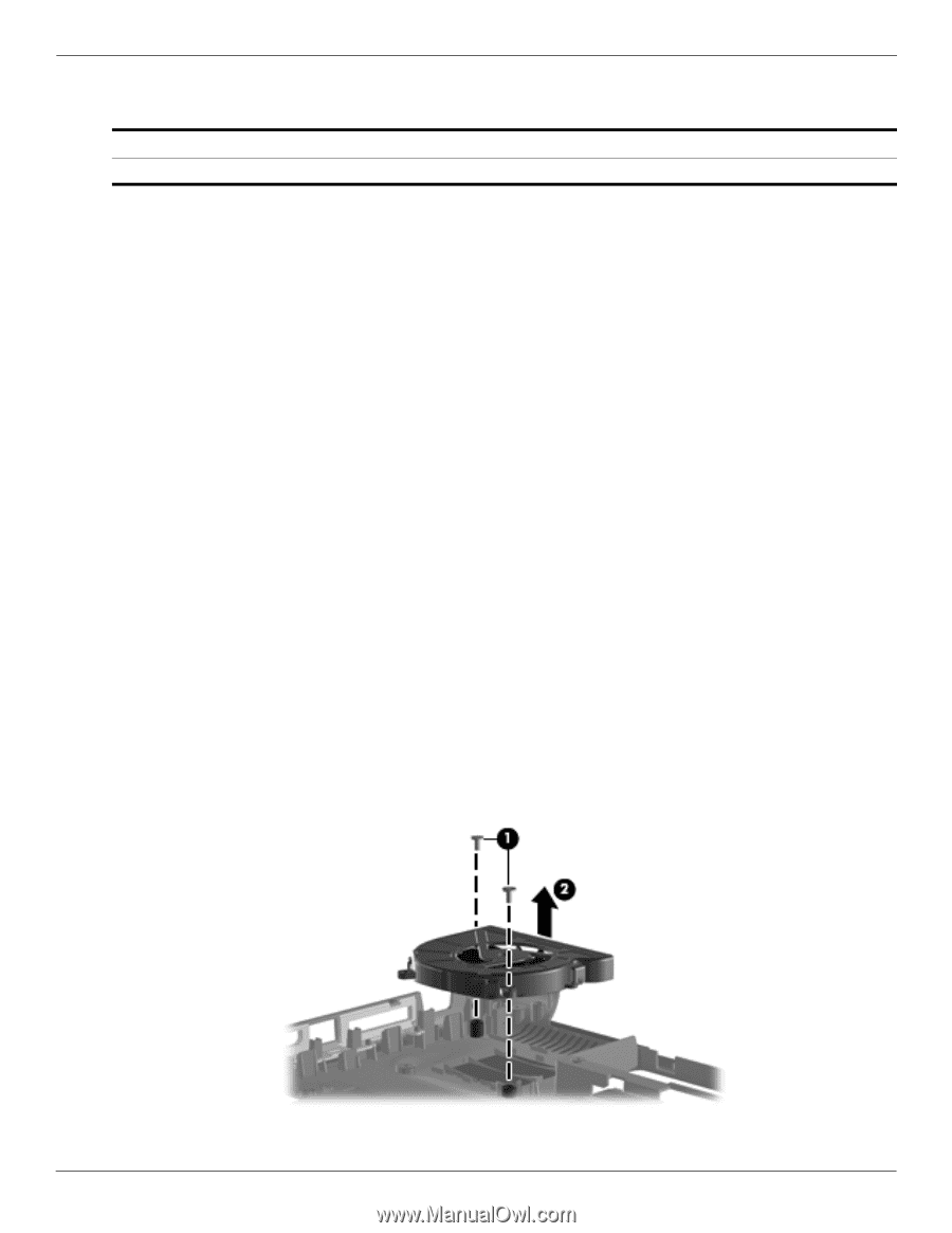
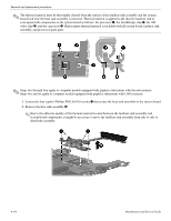
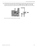
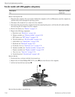
Removal and replacement procedures Fan (for models with UMA graphics subsystems) Description Fan Spare part number 486844-001 Before removing the fan: 1. Shut down the computer. If you are unsure whether the computer is off or in Hibernation, turn the computer on, and then shut it down through the operating system. 2. Disconnect all external devices connected to the computer. 3. Disconnect the power from the computer by first disconnecting the power cord from the AC outlet and then disconnecting the AC adapter from the computer. 4. Remove the battery (see "Battery" on page 4-7). 5. Remove the following components: a. Hard drive (see "Hard drive" on page 4-8) b. Memory module (see "Memory module" on page 4-10) c. RTC battery (see "RTC battery" on page 4-12) d. WLAN module (see "WLAN module" on page 4-14) e. Optical drive (see "Optical drive" on page 4-20) f. Keyboard (see "Keyboard" on page 4-21) g. Keyboard cover (see "Keyboard cover" on page 4-23) h. Speaker assembly (see "Speaker assembly" on page 4-25) i. Display assembly (see "Display assembly" on page 4-27) j. Top cover (see "Top cover" on page 4-35) k. System board (see "System board" on page 4-48) Remove the fan: 1. Position the base enclosure with the front toward you. 2. Remove the two black Phillips PM2.5×5.0 screws 1 that secure the fan to the computer. 3. Lift the fan from the base enclosure 2. Reverse this procedure to install the fan. 4-56 Maintenance and Service Guide
-
 1
1 -
2
-
3
-
4
-
5
-
6
-
7
-
8
-
9
-
10
-
11
-
12
-
13
-
14
-
15
-
16
-
17
-
18
-
19
-
20
-
21
-
22
-
23
-
24
-
25
-
26
-
27
-
28
-
29
-
30
-
31
-
32
-
33
-
34
-
35
-
36
-
37
-
38
-
39
-
40
-
41
-
42
-
43
-
44
-
45
-
46
-
47
-
48
-
49
-
50
-
51
-
52
-
53
-
54
-
55
-
56
-
57
-
58
-
59
-
60
-
61
-
62
-
63
-
64
-
65
-
66
-
67
-
68
-
69
-
70
-
71
-
72
-
73
-
74
-
75
-
76
-
77
-
78
-
79
-
80
-
81
-
82
-
83
-
84
-
85
-
86
-
 87
87 -
 88
88 -
 89
89 -
 90
90 -
 91
91 -
 92
92 -
 93
93 -
 94
94 -
 95
95 -
 96
96 -
 97
97 -
98
-
99
-
100
-
101
-
102
-
103
-
104
-
105
-
106
-
107
-
108
-
109
-
110
-
111
-
112
-
113
-
114
-
115
-
116
-
117
-
118
-
119
-
120
-
121
-
122
-
123
-
124
-
125
-
126
-
127
-
128
-
129
-
130
-
131
-
132
-
133
-
134
 |
 |