D-Link DSN-3400-10 User's Manual for DSN-3200-10 Valid for firmware 1.6.1
D-Link DSN-3400-10 - xStack Storage Area Network Array Hard Drive Manual
 |
UPC - 790069299766
View all D-Link DSN-3400-10 manuals
Add to My Manuals
Save this manual to your list of manuals |
D-Link DSN-3400-10 manual content summary:
- D-Link DSN-3400-10 | User's Manual for DSN-3200-10
Valid for firmware 1.6.1 - Page 1
xStack Storage TM D-Link xStack Storage iSCSI SAN Arrays Managed SAN Solutions DSN-3200 & DSN-3400 User's Guide Version 2.0 - D-Link DSN-3400-10 | User's Manual for DSN-3200-10
Valid for firmware 1.6.1 - Page 2
to change without notice. The only warranties for D-Link products and services are set forth in the express warranty statements accompanying such products and services. Nothing herein should be construed as constituting an additional warranty. D-Link shall not be liable for technical or editorial - D-Link DSN-3400-10 | User's Manual for DSN-3200-10
Valid for firmware 1.6.1 - Page 3
never need to replace it. However, should you need to replace it, consult your service documentation. Do not dispose of the battery along with household waste. Contact your local United States government. Please contact D-Link Systems, Inc. for any export compliance questions. xStack Storage User - D-Link DSN-3400-10 | User's Manual for DSN-3200-10
Valid for firmware 1.6.1 - Page 4
Version 1.0 Version 1.1 Version 2.0 Date Notes August 10, 2006 March 7, 2007 Version 1.1, replaces Version 1.0 - Revises drive numbering schema to reflect proper drive numbers 0 through 14 instead of 1 through 15. September 20, 2007 Version 2.0, replaces Version 1.1 - Revisions include - D-Link DSN-3400-10 | User's Manual for DSN-3200-10
Valid for firmware 1.6.1 - Page 5
Preface This User's Guide assumes that the user is computer literate and is familiar with Storage Array Products, has a basic understanding of storage products and concepts, and understands the Host Operating Software supported by this product Typographic Conventions Notes Notes provide information - D-Link DSN-3400-10 | User's Manual for DSN-3200-10
Valid for firmware 1.6.1 - Page 6
to Friday 8:00am - 5:00pm PST/PDT D-Link Technical Support over the Internet: • http://support.dlink.com Tech Support for customers within Canada: D-Link Technical Support over the Telephone Please see our support site for current number: • http://support.dlink.ca • Monday to Friday 7:30am to 9:00pm - D-Link DSN-3400-10 | User's Manual for DSN-3200-10
Valid for firmware 1.6.1 - Page 7
31 3.8 Connecting to the xStack Storage DSN-3400 Host Network Connection Port .......... 31 3.9 Connecting to the xStack Storage Management Port 32 3.10 Connecting the Battery Pack 33 3.11 Connecting 49 5.2.1 Menu / Tool Bar Area 50 5.2.2 Resources Pane 51 xStack Storage User's Guide vii - D-Link DSN-3400-10 | User's Manual for DSN-3200-10
Valid for firmware 1.6.1 - Page 8
IP Route Tables 85 5.4.10 Modifying System TCP/IP 102 Chapter 6 Monitoring the xStack Storage 104 6.1 Viewing Enclosure Information 105 6.2 Viewing Log Messages 106 6.3 Viewing, Modifying, and Deleting xStack Storage Array Tasks 108 6.4 Viewing Server SMI Information 109 6.5 Viewing Firmware - D-Link DSN-3400-10 | User's Manual for DSN-3200-10
Valid for firmware 1.6.1 - Page 9
FRUs 146 D.1 Installing the Battery Pack 146 D.2 Installing Memory 149 D.3 Installing or Replacing SATA Drives 151 Appendix E Upgrading Firmware ...161 Appendix F Hardware Enclosures...163 F.1 Front View 163 F.2 Back View 163 Appendix G Acronyms and Abbreviations 165 xStack Storage - D-Link DSN-3400-10 | User's Manual for DSN-3200-10
Valid for firmware 1.6.1 - Page 10
x Contents - D-Link DSN-3400-10 | User's Manual for DSN-3200-10
Valid for firmware 1.6.1 - Page 11
availability, serviceability, and performance firmware stack controlled by firmware DSN-3400 provides a single 10GbE XFP-transceiver interface (transceiver sold separately) accessed via the back panel. The xStack Storage Array's back panel also has a 10/100 portal, and Link Aggregation Group (LAG - D-Link DSN-3400-10 | User's Manual for DSN-3200-10
Valid for firmware 1.6.1 - Page 12
network connections. Table 1-1 xStack Storage Array Models Model DSN-3200 DSN-3400 Description Maximum number of host network iSCSI connections: Eight RJ network iSCSI connections: One XFP transceiver host network connection Speed: 10 GbE Maximum number of internal SATA drives: 15 Maximum amount - D-Link DSN-3400-10 | User's Manual for DSN-3200-10
Valid for firmware 1.6.1 - Page 13
10 GbE models provide an easy transition to faster Ethernet connectivity. Eight copper 1Gb (802.3ab) Ethernet network ports on the DSN-3200 One XFP 10Gb Ethernet port on the DSN-3400 availability Three hot-swappable cooling fans Supports Self-Monitoring Analysis and Reporting Technology Guide 13 - D-Link DSN-3400-10 | User's Manual for DSN-3200-10
Valid for firmware 1.6.1 - Page 14
1.3 System Overview Figure 1-1 shows a typical Storage Area Network (SAN) configuration in which xStack Storage Array can be used. The Storage Area Network portion of this diagram is a private high-speed Ethernet network that is dedicated to the exchange of data between the network servers and the - D-Link DSN-3400-10 | User's Manual for DSN-3200-10
Valid for firmware 1.6.1 - Page 15
the xStack Storage Array enclosure. Figure 2-1 shows the removable front bezel along with the drive bays and major components. Figure 2-1 Front View of the xStack DSN-3000 Series Enclosure When installed, the front bezel uses pipes to pass light from the LEDs behind it to the front for viewing. The - D-Link DSN-3400-10 | User's Manual for DSN-3200-10
Valid for firmware 1.6.1 - Page 16
activity and fault LED and a drive power LED. Table 2-1 describes the front panel LEDs and their functions. Table 2-1 Front Panel LED indicators on the DSN-3000 series enclosure LED Color Meaning Power Green ON Power is applied to the system Boot and Fault Green ON Red ON Successful boot - D-Link DSN-3400-10 | User's Manual for DSN-3200-10
Valid for firmware 1.6.1 - Page 17
tray and removing it with the handle as shown in Figure 2-2 and Figure 2-3. Figure 2-2 Drive and Tray Removal Figure 2-3 Remove Drive/Tray xStack Storage User's Guide 17 - D-Link DSN-3400-10 | User's Manual for DSN-3200-10
Valid for firmware 1.6.1 - Page 18
Removal of a populated drive/tray assembly can have unforeseen effects including the loss of all data in a volume. A drive can be part of a volume that may or may not be redundant. Before removing a drive from an operating xStack Storage Array, make sure it is the correct one. 18 Chapter 2 - D-Link DSN-3400-10 | User's Manual for DSN-3200-10
Valid for firmware 1.6.1 - Page 19
2-6 until you hear the green locking mechanism click. Figure 2-4 Drive/Tray Installation Figure 2-5 Press Here Until You See the Lever Move Inwards xStack Storage User's Guide 19 - D-Link DSN-3400-10 | User's Manual for DSN-3200-10
Valid for firmware 1.6.1 - Page 20
Figure 2-6 Press Lever Inwards Until it Locks 20 Chapter 2 Identifying Hardware Components - D-Link DSN-3400-10 | User's Manual for DSN-3200-10
Valid for firmware 1.6.1 - Page 21
describe the hardware components on the rear of the xStack Storage Array's enclosure. Figure 2-7 shows the major components. Figure 2-7 Rear View of the xStack Storage DSN-3200 Enclosure xStack Storage User's Guide 21 - D-Link DSN-3400-10 | User's Manual for DSN-3200-10
Valid for firmware 1.6.1 - Page 22
2.2.1 Switches The rear panel of the xStack Storage unit enclosure has two switches as shown in Figure 2-8. Table 2-2 identifies the switches and their function. Switch Power Reset Figure 2-8 Power and Reset Switches Table 2-2 Power and Reset Switches Function Description Applies power to the - D-Link DSN-3400-10 | User's Manual for DSN-3200-10
Valid for firmware 1.6.1 - Page 23
One DB9 RS-232-C diagnostic port One RJ-45 Fast Ethernet management port Figure 2-9 shows the hardware components on the back of the xStack Storage DSN-3200 enclosure Figure 2-9 External Interfaces on the xStack Storage DSN-3200 Enclosure xStack Storage User's Guide 23 - D-Link DSN-3400-10 | User's Manual for DSN-3200-10
Valid for firmware 1.6.1 - Page 24
DSN-3200 enclosure. Table 2-3 Host Network Connection LED Indicators on the xStack DSN-3200 Link is operational. Data is being transmitted or received on the RJ-45 port. Connection has been established at 10 Mbps. Connection has been established at 100 Mbps. Data is being sent or received at 10 - D-Link DSN-3400-10 | User's Manual for DSN-3200-10
Valid for firmware 1.6.1 - Page 25
2-10 shows the hardware components on the back of the xStack DSN-3400. Figure 2-10 External Interfaces on the xStack DSN-3400 Enclosure 2.2.2.4 DSN-3400 the xStack DSN-3400 enclosure. Table 2-5 Host Network Connection LED Indicators on the xStack DSN-3400 Enclosure LED Tx Link Rx Link Color OFF - D-Link DSN-3400-10 | User's Manual for DSN-3200-10
Valid for firmware 1.6.1 - Page 26
on the xStack DSN-3400 Enclosure LED Activity/Link Port Speed Color Green ON Green Blinking Yellow OFF Yellow ON OFF Yellow Meaning Link is operational. Data is being transmitted or received on the RJ-45 port. Connection has been established at 10 Mbps. Connection has been established at 100 Mbps - D-Link DSN-3400-10 | User's Manual for DSN-3200-10
Valid for firmware 1.6.1 - Page 27
sturdy, level surface that can support the unit. A fully instructions in the documentation for the rack. The operating ambient temperature of rack-mounted equipment must not exceed the maximum rated ambient temperature of 104 degrees F (70 degrees C). The air flow clearances specified in this guide - D-Link DSN-3400-10 | User's Manual for DSN-3200-10
Valid for firmware 1.6.1 - Page 28
: - xStack Storage Array - Three power cords - Console cable (straight-through female DB9 to female DB9) - Rackmount rail kit - CD including this User Guide 5. Inspect the xStack Storage Array thoroughly. If you see any signs of damage, notify a sales representative and/or the shipping agency. 28 - D-Link DSN-3400-10 | User's Manual for DSN-3200-10
Valid for firmware 1.6.1 - Page 29
want to use the xStack Storage Array's Link Aggregation feature, the switch must support LAGs. xStack DSN-3200 Users A static IP address for each SAN (the xStack Storage auto-senses the cable type used). xStack DSN-3400 Users A static IP address for the host network connection. Either Guide 29 - D-Link DSN-3400-10 | User's Manual for DSN-3200-10
Valid for firmware 1.6.1 - Page 30
3.5 Installing the xStack Storage Array without a Rack When installing the xStack Storage Array on a desktop or shelf, allow enough ventilation space between the xStack Storage unit and any other objects in the vicinity. In particular, be sure not to block the air vents on the front and back of the - D-Link DSN-3400-10 | User's Manual for DSN-3200-10
Valid for firmware 1.6.1 - Page 31
making these connections. 3.8 Connecting to the xStack Storage DSN-3400 Host Network Connection Port The DSN-3400 host network connection consists of a single 10 GbE host network XFP transceiver interface. The XFP module can the other end of the cable to your SAN. xStack Storage User's Guide 31 - D-Link DSN-3400-10 | User's Manual for DSN-3200-10
Valid for firmware 1.6.1 - Page 32
xStack Storage unit, the management port is the rightmost RJ-45 connector: - To view this port on the xStack DSN-3200, see Figure 2-9 on page 23. - To view this port on the xStack DSN-3400, see Error! Reference source not found. on page 25. If you want to configure the xStack Storage Array - D-Link DSN-3400-10 | User's Manual for DSN-3200-10
Valid for firmware 1.6.1 - Page 33
3.10 Connecting the Battery Pack The xStack Storage Array comes equipped with a battery pack to provide back up of the buffer cache contents is attached to the controller board through a 3-pin connector at J-35. Figure 3-1 Battery Pack Installed on xStack Controller xStack Storage User's Guide 33 - D-Link DSN-3400-10 | User's Manual for DSN-3200-10
Valid for firmware 1.6.1 - Page 34
3.11 Connecting the Power Cords The receptacles for connecting the xStack Storage Array's three power cords appears on the back of the unit as seen in Figure 3-2. To connect a power cord for each of the power supplies three redundant power modules, use the following procedure. 1. Plug the female end - D-Link DSN-3400-10 | User's Manual for DSN-3200-10
Valid for firmware 1.6.1 - Page 35
xStack Storage unit runs its startup process, which takes from 4 to 5 minutes to complete. The front panel Link Status LEDs for the SATA drive LEDs may flash. When the Boot and Fault Ready LED turns green the xStack Switch and Reset Switch Located on Rear of Enclosure xStack Storage User's Guide 35 - D-Link DSN-3400-10 | User's Manual for DSN-3200-10 Valid for firmware 1.6.1 - Page 36
- D-Link DSN-3400-10 | User's Manual for DSN-3200-10
Valid for firmware 1.6.1 - Page 37
Welcome screen shown in Figure 4-1. Click the Start button in the Welcome screen to continue and proceed to Section 4.2. Figure 4-1 Welcome Screen xStack Storage User's Guide 37 - D-Link DSN-3400-10 | User's Manual for DSN-3200-10
Valid for firmware 1.6.1 - Page 38
4.2 Entering Initial Management Port Settings After you click the Next button in the Welcome screen, the Management Port screen in Figure 4-2 appears. This screen lets you specify the settings that client computers will use to access the xStack Storage Array management console. The values you enter - D-Link DSN-3400-10 | User's Manual for DSN-3200-10
Valid for firmware 1.6.1 - Page 39
an asterisk (*). Retype the same case-sensitive password typed in the Password field. For security, each typed character appears as an asterisk (*). xStack Storage User's Guide 39 - D-Link DSN-3400-10 | User's Manual for DSN-3200-10
Valid for firmware 1.6.1 - Page 40
Firmware 1.4.0.27 and later will not allow the primary admin account "admin" to be deleted. For security, please be sure to change the default admin account's - D-Link DSN-3400-10 | User's Manual for DSN-3200-10
Valid for firmware 1.6.1 - Page 41
emails. If you need to change these initial settings at a later time, use the procedure described in Chapter 5. Figure 4-5 Email Notification Screen xStack Storage User's Guide 41 - D-Link DSN-3400-10 | User's Manual for DSN-3200-10
Valid for firmware 1.6.1 - Page 42
Setting Enable Email Support SMTP Server IP Address Port Number From To Table 4-4 Email in Figure 4-6 appears, with a summary of the initial settings you specified in the OOBE setup wizard. Review the settings to ensure they are correct. If you need to change a setting, click the Previous button - D-Link DSN-3400-10 | User's Manual for DSN-3200-10
Valid for firmware 1.6.1 - Page 43
alerts you to change the settings on your management PC, so you can access the xStack Storage Array console. Figure 4-7 Restart Message xStack Storage User's Guide 43 - D-Link DSN-3400-10 | User's Manual for DSN-3200-10
Valid for firmware 1.6.1 - Page 44
44 Chapter 4 Starting the xStack Storage Array for the First Time - D-Link DSN-3400-10 | User's Manual for DSN-3200-10
Valid for firmware 1.6.1 - Page 45
5.6, Managing xStack Storage Array Configurations on page 99 Section 5.7, Restarting the xStack Storage Array on page 101 Section 5.8, Shutting Down the Management Console on page 102 Section 5.9, Shutting Down the xStack Storage Array on page 102 xStack Storage User's Guide 45 - D-Link DSN-3400-10 | User's Manual for DSN-3200-10
Valid for firmware 1.6.1 - Page 46
5.1 Launching the xStack Storage Management Console The following procedure describes how to launch the xStack Storage Array's management console. This procedure assumes that: The xStack Storage Array is powered-up. A PC with an installed Web browser and Java v1.4.2 is connected to the management - D-Link DSN-3400-10 | User's Manual for DSN-3200-10
Valid for firmware 1.6.1 - Page 47
Figure 5-1 xStack Storage Array Startup Screen Figure 5-2 xStack Storage Log in Screen xStack Storage User's Guide 47 - D-Link DSN-3400-10 | User's Manual for DSN-3200-10
Valid for firmware 1.6.1 - Page 48
Figure 5-3 xStack Storage Management Console Main Screen 48 Chapter 5 Configuring the xStack Storage Array - D-Link DSN-3400-10 | User's Manual for DSN-3200-10
Valid for firmware 1.6.1 - Page 49
5.2 Understanding the Main Screen Figure 5-4 shows the areas of the xStack Storage Array's management console main screen. Resources Pane Menu/Tool Bar Area Main Display Area Footer Figure 5-4 Parts of the xStack Storage Management Console Main Screen xStack Storage User's Guide 49 - D-Link DSN-3400-10 | User's Manual for DSN-3200-10
Valid for firmware 1.6.1 - Page 50
5.2.1 Menu / Tool Bar Area The Menu/Tool Bar Area appears at the top of the xStack Storage management console window. This area contains the following components (Figure 5-5): Title bar. The title bar shows the name of the application. On the right side of the title bar are the standard Windows - D-Link DSN-3400-10 | User's Manual for DSN-3200-10
Valid for firmware 1.6.1 - Page 51
is expanded, a minus sign (-) replaces the plus sign. Clicking the minus sign collapses the item. In this Guide, you will see references to the "active tab." The active tab is the tab that is on top (in Tab Example of Logical Resources Tab Figure 5-6 Resources Pane xStack Storage User's Guide 51 - D-Link DSN-3400-10 | User's Manual for DSN-3200-10
Valid for firmware 1.6.1 - Page 52
enhance viewing, the port icons are color coded (black = link is down, green = link is up). 5.2.2.2 Logical Resources Tab The Logical Resources tab a volume is reduced (for example, if a physical drive fails), the firmware will automatically move a drive from the Available Pool to the Blade A Base - D-Link DSN-3400-10 | User's Manual for DSN-3200-10
Valid for firmware 1.6.1 - Page 53
it. For more information about the screens that can appear in the main display area, refer to Chapter 6. Figure 5-7 Main Display Area xStack Storage User's Guide 53 - D-Link DSN-3400-10 | User's Manual for DSN-3200-10
Valid for firmware 1.6.1 - Page 54
5.2.4 Footer The footer appears at the bottom of the xStack Storage management console window. The footer shows status information when appropriate. If you select Blade A Base Pool in the Logical Resources tab, for example, the words Blade A Base Pool appear in the footer (see Figure 5-8). Selecting - D-Link DSN-3400-10 | User's Manual for DSN-3200-10
Valid for firmware 1.6.1 - Page 55
being able to manage storage or add/edit user accounts. The admin account cannot be deleted in firmware version 1.4.0.27 and above. For security, please be sure to change the password for this account. defined (see Figure 5-9). Figure 5-9 User Accounts Screen xStack Storage User's Guide 55 - D-Link DSN-3400-10 | User's Manual for DSN-3200-10
Valid for firmware 1.6.1 - Page 56
3. Click the Add User button. The Add New User dialog box appears (see Figure 5-10). Figure 5-10 Add New User Dialog Box 4. Complete the fields in the dialog box (see Table 5-1). 5. Click OK. The user you defined appears in the User Accounts - D-Link DSN-3400-10 | User's Manual for DSN-3200-10
Valid for firmware 1.6.1 - Page 57
single drive. Redundant No Yes No Yes Yes Striped No No Yes Equivalent to RAID Level - RAID 1 RAID 0 Yes RAID 1+ 0 Yes RAID 5 xStack Storage User's Guide 57 - D-Link DSN-3400-10 | User's Manual for DSN-3200-10
Valid for firmware 1.6.1 - Page 58
through the target. Using the management console, you can create volumes automatically or manually. The automatic method is the fastest way to create volumes. See Section 5.4.1.1.1. The manual method lets you customize and fine-tune volumes. See Section 5.4.1.1.2. 5.4.1.1.1 Creating Volumes - D-Link DSN-3400-10 | User's Manual for DSN-3200-10
Valid for firmware 1.6.1 - Page 59
. Select whether the volume will have no data redundancy or parity or mirror redundancy. For an explanation of these selections, see Table 5-2. xStack Storage User's Guide 59 - D-Link DSN-3400-10 | User's Manual for DSN-3200-10
Valid for firmware 1.6.1 - Page 60
can use the Advanced tab to write-protect the volume and suppress Synch Cache commands from the host (see 5.4.1.4). 5.4.1.1.2 Creating Volumes Manually The following procedure describes how to create volumes manually. With this method, you select the organization and other parameters, and specify - D-Link DSN-3400-10 | User's Manual for DSN-3200-10
Valid for firmware 1.6.1 - Page 61
tab: - Click the Manual Create Volume button on the toolbar. - On the Storage menu, click Manual Create Volume. The Manual Create Volume Wizard launches and Type to Create screen appears (see Figure 5-13). Figure 5-13 Manual Create Volume Wizard - Select Volume Type to Create Screen 6. Complete - D-Link DSN-3400-10 | User's Manual for DSN-3200-10
Valid for firmware 1.6.1 - Page 62
Figure 5-14 Manual Create Volume Wizard - Select the Drives Screen 8. In the left box, select the drives from which the volume will be allocated, then click the Add button. Observe the following guidelines when selecting drives: - JBOD volumes support a minimum of 1 drive and can span across - D-Link DSN-3400-10 | User's Manual for DSN-3200-10
Valid for firmware 1.6.1 - Page 63
a volume larger than the selected drives can support, an error message appears after you click the a smaller volume. Table 5-6 Manual Create Volume Wizard - Select Volume to write-protect the volume and suppress Synch Cache commands from the host (see 5.4.1.4). 5.4.1.2 Expanding a Volume Guide 63 - D-Link DSN-3400-10 | User's Manual for DSN-3200-10
Valid for firmware 1.6.1 - Page 64
size of the volume. 4. Click OK. 5. When the Expand Volume started message appears (see Figure 5-16), click OK. If the selected volume cannot support the specified size, an error message appears. If this occurs, specify a smaller size. Figure 5-16 Expand Volume Message 64 Chapter 5 Configuring the - D-Link DSN-3400-10 | User's Manual for DSN-3200-10
Valid for firmware 1.6.1 - Page 65
box from None to Parity, which would change the Volume's organization to Parity. 3. Review the settings in the displayed screen and change them as necessary. 4. Click the Finish to write-protect the volume and disable Sync Cache commands from a host. Figure 5-17 Advanced Screen xStack Storage User - D-Link DSN-3400-10 | User's Manual for DSN-3200-10
Valid for firmware 1.6.1 - Page 66
screen, the change takes effect immediately. 5.4.1.4.2 Disabling Sync Cache Commands Some applications that stream media such as video can suffer performance problems if the host file system sends the SCSI Sync Cache command repeatedly. This command tells the xStack Storage Array to write to disk - D-Link DSN-3400-10 | User's Manual for DSN-3200-10
Valid for firmware 1.6.1 - Page 67
. If media errors are found, this task corrects the errors. 1. Click the volume on which you want to perform the media scan. xStack Storage User's Guide 67 - D-Link DSN-3400-10 | User's Manual for DSN-3200-10
Valid for firmware 1.6.1 - Page 68
2. Perform one of the following steps: - On the Storage menu, click Media Scan. - Right-click and click Media Scan. Either step starts the scan operation and displays a message informing you that the scan started successfully. 3. Click OK to remove the message. After you start a media scan task, you - D-Link DSN-3400-10 | User's Manual for DSN-3200-10
Valid for firmware 1.6.1 - Page 69
DSN-3200: The default number of LAGs is eight. DSN-3400: The default number of LAGs is one. Since this model has only one data port, it does not support xStack Storage Array in this configuration. Link Aggregation is a way to combine ( creates resilient and redundant links. These capabilities are - D-Link DSN-3400-10 | User's Manual for DSN-3200-10
Valid for firmware 1.6.1 - Page 70
can allow better overall bandwidth utilization. Figure 5-20. Example of Link Aggregation between the xStack Storage Array and a Gigabit LAGs, you can indicate whether the LAG is to support a virtual LAN (VLAN). All xStack Storage Array models support eight VLANs, one for each IP address. As you - D-Link DSN-3400-10 | User's Manual for DSN-3200-10
Valid for firmware 1.6.1 - Page 71
5-8 Create Link Aggregation Group Wizard - LAG Parameters Screen Settings Setting MTU Size Ethernet Encapsulation VLAN Supported Auto Negotiation the network. Ethernet_II Ethernet_802.3 Check this box to have the LAG support a Virtual Network (VLAN). This option is unavailable. 6. Click the - D-Link DSN-3400-10 | User's Manual for DSN-3200-10
Valid for firmware 1.6.1 - Page 72
Figure 5-22 Create Link Aggregation Group Wizard - Add/Delete Ethernet Ports Screen 7. To add Ethernet ports, select one or more ports in the left box and click Add to - D-Link DSN-3400-10 | User's Manual for DSN-3200-10
Valid for firmware 1.6.1 - Page 73
size of a packet that can be transferred in one frame over a network. This value indicates the requested speed for transmitting and sending packets. For the DSN-3200, the choices are Auto Detect, 100 Mbps, and 10 Mbps. For the DSN-3400, the only choice is 10GB. xStack Storage User's Guide 73 - D-Link DSN-3400-10 | User's Manual for DSN-3200-10
Valid for firmware 1.6.1 - Page 74
5.4.3.3 Adding or Deleting Physical Ports in a LAG There may be times when you want to add physical ports to or delete physical ports from a LAG. The following steps describe this procedure. As you add or remove physical ports, record the information in Appendix B. 1. In the Logical Resources tab, - D-Link DSN-3400-10 | User's Manual for DSN-3200-10
Valid for firmware 1.6.1 - Page 75
Create Network Port. Either step starts the Create Network Portal Wizard and displays the Set the IP Address screen (see Figure 5-25). xStack Storage User's Guide 75 - D-Link DSN-3400-10 | User's Manual for DSN-3200-10
Valid for firmware 1.6.1 - Page 76
data port. After you create the network portals, you can monitor their status using the Portals Information screen (see Section 6.15). Table 5-10 Create Network Portal Wizard - Set the IP Address Screen Settings Setting IP Address Subnet Mask Default Gateway Description Enter the IP address for - D-Link DSN-3400-10 | User's Manual for DSN-3200-10
Valid for firmware 1.6.1 - Page 77
to permit access to the volumes on an xStack Storage Array by an initiator. The xStack Storage Array supports up to 1024 iSCSI target nodes. After you create one or more volumes, iSCSI initiators, and LAGs Create iSCSI Node Wizard - Enter iSCSI Node Information Screen xStack Storage User's Guide 77 - D-Link DSN-3400-10 | User's Manual for DSN-3200-10
Valid for firmware 1.6.1 - Page 78
appears as an asterisk (*). If you decide not to specify a CHAP secret now, you can do so in the future using the Set CHAP Secret command in the iSCSI menu. Figure 5-27. Create iSCSI Node Wizard - Enter iSCSI Node Information Screen with CHAP Secret Field Shown 4. Click Next. The Configure iSCSI - D-Link DSN-3400-10 | User's Manual for DSN-3200-10
Valid for firmware 1.6.1 - Page 79
Node Wizard - Configure iSCSI Node Parameters Screen (Connection Settings Tab) 6. Click Next. The Modify iSCSI Network Portal screen appears (see Figure 5-30). xStack Storage User's Guide 79 - D-Link DSN-3400-10 | User's Manual for DSN-3200-10
Valid for firmware 1.6.1 - Page 80
Figure 5-30. Create iSCSI Node Wizard - Modify iSCSI Network Portals Screen 7. In the left column, click the IP address of the network portal(s) allowed for this target node and click Add to move the IP address to the right list. To select additional IP addresses, repeat this step. (To remove an IP - D-Link DSN-3400-10 | User's Manual for DSN-3200-10
Valid for firmware 1.6.1 - Page 81
click the iSCSI initiator in the right box and click Remove to return the iSCSI initiator to the left box. 10. Click Next. The Volume Access Right screen appears (see Figure 5-32). Figure 5-32. Create iSCSI Node Wizard , hold down the Ctrl key and click the volume. xStack Storage User's Guide 81 - D-Link DSN-3400-10 | User's Manual for DSN-3200-10
Valid for firmware 1.6.1 - Page 82
To remove a volume from the right box, click the volume in the right box and click Remove to return the volume to the left box. 10. Click Finish. On completion, the xStack Storage Array assigns a world-wide unique name to the iSCSI target node. You can use the procedure in Section 6. - D-Link DSN-3400-10 | User's Manual for DSN-3200-10
Valid for firmware 1.6.1 - Page 83
xStack Storage Array from the iSCSI initiator computer. For example, using the DSN-3200: 1. Use an Ethernet RJ-45 cable to connect the appropriate the iSCSI initiator. For more information, please refer to the instructions for your iSCSI initiator software. 3. Use the initiator software 's Guide 83 - D-Link DSN-3400-10 | User's Manual for DSN-3200-10
Valid for firmware 1.6.1 - Page 84
Either step displays the Modify iSCSI Port dialog box, with the current iSCSI port number shown (see Figure 5-34). Figure 5-34 Modify iSCSI Port Dialog Box 2. Enter a new value for the iSCSI port. 3. Click OK. The new iSCSI port number will take effect after the next controller restart. 5.4.8 - D-Link DSN-3400-10 | User's Manual for DSN-3200-10
Valid for firmware 1.6.1 - Page 85
the default priority level (0 = highest priority, 10 = lowest priority). 3. Click OK. 5.4.9 Adding routing table. If a route being used encounters problems, you can use the management console to add delete routes. 1. On the View menu, click View Manual Route. The View Route Table appears, with the - D-Link DSN-3400-10 | User's Manual for DSN-3200-10
Valid for firmware 1.6.1 - Page 86
2. To add a route to the routing table, click the Add button. Then, when the dialog box in Figure 5-37 appears, complete the fields and click OK. As you add route entries, record the information in Appendix B. Figure 5-37. Adding a Route Table 3. To delete a route, click the route in the View Route - D-Link DSN-3400-10 | User's Manual for DSN-3200-10
Valid for firmware 1.6.1 - Page 87
5.4.10 Modifying System TCP/IP Settings You can use the management console to view and change the system's TCP/IP settings. 1. Click the Figure 5-38. Modify System TCP/IP Settings Dialog Box 3. Complete the fields in the dialog box (see Table 5-13). 4. Click OK. xStack Storage User's Guide 87 - D-Link DSN-3400-10 | User's Manual for DSN-3200-10
Valid for firmware 1.6.1 - Page 88
if intermediate systems on the path to the remote system cannot support the default packet size, the xStack Storage Array ignores their requests administrator tried to perform an Automatic Volume Creation with both sliders at 10 (their maximum values), the volume is created using 11 drives, without - D-Link DSN-3400-10 | User's Manual for DSN-3200-10
Valid for firmware 1.6.1 - Page 89
Drive task. 2. Right-click and select the Suspend option. To resume the Down Drive operation, right click and select the Resume option. xStack Storage User's Guide 89 - D-Link DSN-3400-10 | User's Manual for DSN-3200-10
Valid for firmware 1.6.1 - Page 90
that a Fibre Channel SAN does. Because iSNS can emulate Fibre Channel fabric services and manage both iSCSI and Fibre Channel devices, an iSNS server can entire storage network. The xStack Storage Array management console supports two iSNS configuration options: The xStack Storage Array management - D-Link DSN-3400-10 | User's Manual for DSN-3200-10
Valid for firmware 1.6.1 - Page 91
dialog box (see Table 5-15). 5. Click OK. The settings are saved and the xStack Storage Array registers itself with the iSNS server. xStack Storage User's Guide 91 - D-Link DSN-3400-10 | User's Manual for DSN-3200-10
Valid for firmware 1.6.1 - Page 92
the iSNS service. Enter the subnet mask of the server running the iSNS service. Enter the port number on which the server running the iSNS service s listening. as parity or media scans. When you create a task, you specify the day and time when it is to be performed and whether the task will repeat - D-Link DSN-3400-10 | User's Manual for DSN-3200-10
Valid for firmware 1.6.1 - Page 93
start. You can use the controls below the calendar to move to the previous year, previous month, next month, or next year. xStack Storage User's Guide 93 - D-Link DSN-3400-10 | User's Manual for DSN-3200-10
Valid for firmware 1.6.1 - Page 94
5.4.15 Setting the System Battery Policy If your xStack Storage Array has an onboard battery, the system battery policy defines how contents in cache memory are handled if the battery is not fully charged. By default, the xStack Storage Array is configured to buffer all I/O in cache memory. You can, - D-Link DSN-3400-10 | User's Manual for DSN-3200-10
Valid for firmware 1.6.1 - Page 95
the event log text file to reside. 5. In the File name field, enter a name for the event log text file. 6. Click OK. xStack Storage User's Guide 95 - D-Link DSN-3400-10 | User's Manual for DSN-3200-10
Valid for firmware 1.6.1 - Page 96
5.5 Changing Initial Configuration Settings When you started the xStack Storage Array for the first time, you specified the unit's initial settings using the OOBE setup wizard. You may need to change these settings in the future. For example, you may need to change the date and time if time changes - D-Link DSN-3400-10 | User's Manual for DSN-3200-10
Valid for firmware 1.6.1 - Page 97
step displays the xStack Storage Date and Time dialog box (see Figure 5-47). Figure 5-47 xStack Storage Date and Time Dialog Box xStack Storage User's Guide 97 - D-Link DSN-3400-10 | User's Manual for DSN-3200-10
Valid for firmware 1.6.1 - Page 98
). 4. Click OK. 5. Restart the xStack Storage Array for the new settings to take effect. Table 5-20. xStack Storage Date and Time Dialog Box Settings Setting Timezone System Date System Time Description Select the appropriate timezone from the drop-down list. Use - D-Link DSN-3400-10 | User's Manual for DSN-3200-10
Valid for firmware 1.6.1 - Page 99
Click OK. Table 5-21. Configure Email Notification Dialog Box Settings Setting Enable Email Notification Support From Address To Address SMTP Server SMTP Port Description Click this option to enable email notifications ). Figure 5-49 Save xStack Storage Dialog Box xStack Storage User's Guide 99 - D-Link DSN-3400-10 | User's Manual for DSN-3200-10
Valid for firmware 1.6.1 - Page 100
restore the configuration. (Or click No to keep the current configuration.) If you clicked Yes the xStack Storage Array restarts and loads the selected configuration. 100 Chapter 5 Configuring the xStack Storage Array - D-Link DSN-3400-10 | User's Manual for DSN-3200-10
Valid for firmware 1.6.1 - Page 101
To return the xStack Storage Array to its factory-default settings, use the following procedure. For firmware 1.4.0.27 and later, when you return to the factory-default settings, you are given the choice earlier in this chapter to log into the management console. xStack Storage User's Guide 101 - D-Link DSN-3400-10 | User's Manual for DSN-3200-10
Valid for firmware 1.6.1 - Page 102
(or click No to keep the system running). If you clicked Yes, your management console session ends and the xStack Storage Array is powered off. 102 Chapter 5 Configuring the xStack Storage Array - D-Link DSN-3400-10 | User's Manual for DSN-3200-10
Valid for firmware 1.6.1 - Page 103
xStack Storage User's Guide 103 - D-Link DSN-3400-10 | User's Manual for DSN-3200-10
Valid for firmware 1.6.1 - Page 104
screen Event log messages Log Messages screen Firmware image Firmware Image Info screen xStack Storage enclosure Enclosure Information screen See Section 6.10 6.19 6.16 6.2 6.5 6.1 6.7 6.15 6.17 6.13 6.14 6.18 6.12 6.11 6.10.2 6.10.2 6.4 6.6 6.7 6.9 6.8 104 Chapter 6 Monitoring the xStack - D-Link DSN-3400-10 | User's Manual for DSN-3200-10
Valid for firmware 1.6.1 - Page 105
indicate something unexpected has occurred that may be a serious problem. - Warning messages are yellow. Warning messages indicate that something Storage Array supports Enclosure Services and an error occurs, email notification is sent, the Fault/Ready LED illuminates red (chassis support required) - D-Link DSN-3400-10 | User's Manual for DSN-3200-10
Valid for firmware 1.6.1 - Page 106
among informational, warning, and error messages. The messages are time- and date-stamped, with the most recent entry appearing at the top of the screen. 106 Chapter 6 Monitoring the xStack Storage - D-Link DSN-3400-10 | User's Manual for DSN-3200-10
Valid for firmware 1.6.1 - Page 107
a cautionary message: Alarm messages indicate that a severe condition exists that could potentially cause a problem with resources. The following is an example of an alarm message: To obtain additional information desired. For more information, see Chapter 5. xStack Storage User's Guide 107 - D-Link DSN-3400-10 | User's Manual for DSN-3200-10
Valid for firmware 1.6.1 - Page 108
6.3 Viewing, Modifying, and Deleting xStack Storage Array Tasks When the xStack Storage icon is selected in the Physical Resources tab, you can use the Tasks Info screen to view the xStack Storage Array tasks (see Figure 6-3). Examples of tasks include bad block scan and volume initialization - D-Link DSN-3400-10 | User's Manual for DSN-3200-10
Valid for firmware 1.6.1 - Page 109
Information area has an Edit button you can click to change the SMI server information if necessary. Figure 6-4 SMI Server Information Screen xStack Storage User's Guide 109 - D-Link DSN-3400-10 | User's Manual for DSN-3200-10
Valid for firmware 1.6.1 - Page 110
icon is selected in the Physical Resources tab, you can use the Firmware Image Info screen to view the currently active firmware image being used by the xStack Storage Array (see Figure 6-5). This screen also shows other valid firmware images that have been used with the xStack Storage Array. For - D-Link DSN-3400-10 | User's Manual for DSN-3200-10
Valid for firmware 1.6.1 - Page 111
is color coded (green = online, black = offline. Capacity (the actual usable capacity of the drive) Utilization percentage Allocation Figure 6-6 Storage Group Information xStack Storage User's Guide 111 - D-Link DSN-3400-10 | User's Manual for DSN-3200-10
Valid for firmware 1.6.1 - Page 112
6.7 Viewing Storage Pool Tasks When Blade A Base Pool is selected in the Logical Resources tab, you can use the Tasks Info screen to view tasks scheduled for the storage pool (see Figure 6-7). Examples of tasks include media scan and drive initialization activities. Each row of the Tasks Info screen - D-Link DSN-3400-10 | User's Manual for DSN-3200-10
Valid for firmware 1.6.1 - Page 113
the volume appears in the tab., for example, shows information for a volume named "dlink." The Volume Information screen shows the following information (see Figure 6-8): The volume's durable (s). Figure 6-8 Example of Volume Information for a Volume Named dlink xStack Storage User's Guide 113 - D-Link DSN-3400-10 | User's Manual for DSN-3200-10
Valid for firmware 1.6.1 - Page 114
6.9 Viewing Volume Tasks When you click a volume under Blade A Base Pool, you can use the Task Info screen to view tasks assigned to the selected volume. Each row of the Tasks Info screen corresponds to a task assigned to the volume. The information shown for each task is (see Figure 6-9) The task - D-Link DSN-3400-10 | User's Manual for DSN-3200-10
Valid for firmware 1.6.1 - Page 115
the selected drive as described in the following sections. 6.10.1 Viewing Information About Physical Drives When a drive is 10). Drive number Vendor model Serial number Physical capacity State (for example, online or offline) Microcode level ATA version Supported and actual line speeds Support - D-Link DSN-3400-10 | User's Manual for DSN-3200-10
Valid for firmware 1.6.1 - Page 116
6-11). You may notice a slight delay, as the xStack Storage Array polls this information from the drive (SMART data is polled from the drive every 10 seconds). The third tab displays the SMART attributes in a table (see Figure 6-12). Again, you may notice a slight delay, as the information is polled - D-Link DSN-3400-10 | User's Manual for DSN-3200-10
Valid for firmware 1.6.1 - Page 117
Figure 6-12 Viewing SMART Attributes xStack Storage User's Guide 117 - D-Link DSN-3400-10 | User's Manual for DSN-3200-10
Valid for firmware 1.6.1 - Page 118
6.11 Viewing Target Node Information When a network entity is selected in the Logical Resources tab, you can use the Target Node Info screen to view the session and connection parameters associated with the selected network entity. Figure 6-13 Target Node Info Screen 118 Chapter 6 Monitoring the - D-Link DSN-3400-10 | User's Manual for DSN-3200-10
Valid for firmware 1.6.1 - Page 119
Info screen to view LUN map information for the volume associated with the selected network entity. Figure 6-14 Volume Access Info Screen xStack Storage User's Guide 119 - D-Link DSN-3400-10 | User's Manual for DSN-3200-10
Valid for firmware 1.6.1 - Page 120
6.13 Viewing Initiator Access Information When a network entity is selected in the Logical Resources tab, you can use the Initiator Access Info screen to view iSCSI initiator and access information associated with the selected network entity. Figure 6-15 Initiator Access Info Screen 120 Chapter 6 - D-Link DSN-3400-10 | User's Manual for DSN-3200-10
Valid for firmware 1.6.1 - Page 121
LAG MAC port address - Requested per-port speed - Aggregate LAG speed - Link status - Admin status - Ethernet encapsulation - VLAN support - Auto negotiation - MTU Ethernet Port. This area shows the status of each with the LAG port. Figure 6-16 LAG Port Info Screen xStack Storage User's Guide 121 - D-Link DSN-3400-10 | User's Manual for DSN-3200-10
Valid for firmware 1.6.1 - Page 122
6.15 Viewing Network Portal Information When a network entity is selected in the Logical Resources tab, you can use the Portals Info screen to view the IP address and port number associated with the selected network entity. Figure 6-17 Portals Info Screen 122 Chapter 6 Monitoring the xStack - D-Link DSN-3400-10 | User's Manual for DSN-3200-10
Valid for firmware 1.6.1 - Page 123
Information screen to view the connection parameters and session information for the selected connection (see Figure 6-18). Figure 6-18 Connection Information Screen xStack Storage User's Guide 123 - D-Link DSN-3400-10 | User's Manual for DSN-3200-10
Valid for firmware 1.6.1 - Page 124
6.17 Viewing iSCSI Initiator Information When an iSCSI initiator is selected in the Logical Resources tab, you can use the Initiator Information screen to view information associated with the selected iSCSI initiator (see Figure 6-19). Figure 6-19 Initiator Information Screen 124 Chapter 6 - D-Link DSN-3400-10 | User's Manual for DSN-3200-10
Valid for firmware 1.6.1 - Page 125
the Logical Resources tab, you can use the LUN Map Information screen to view LUN Map information associated with the selected iSCSI initiator (see Figure 6-20 Figure 6-20 LUN Map Information Screen xStack Storage User's Guide 125 - D-Link DSN-3400-10 | User's Manual for DSN-3200-10
Valid for firmware 1.6.1 - Page 126
6.19 Viewing Ethernet Port Information When an Ethernet port is selected in the Physical Resources tab, the main display area shows the physical port information for the selected Ethernet port (see Figure 6-21). Figure 6-21 Physical Port Information 126 Chapter 6 Monitoring the xStack Storage - D-Link DSN-3400-10 | User's Manual for DSN-3200-10
Valid for firmware 1.6.1 - Page 127
application (the upper layers). If ping shows that packets can travel to the network and back, the problem is probably in the upper layers. If packets cannot make the round trip, lower protocol layers may be 7-1 appears. Figure 7-1. Pinging from a Network Portal xStack Storage User's Guide 127 - D-Link DSN-3400-10 | User's Manual for DSN-3200-10
Valid for firmware 1.6.1 - Page 128
2. In the IP Address to Ping field, enter the destination IP address of the host. 3. Click the Ping button. The results of the ping appear in the Results area of the dialog box. 4. When you finish, click the Close button to close the dialog box. 7.2 Pinging from the xStack Storage Array Management - D-Link DSN-3400-10 | User's Manual for DSN-3200-10
Valid for firmware 1.6.1 - Page 129
Live (TTL) PMTU Enabled Parameter Default Value 8960 0 64 True Default Priority Table A-5. Set Default Task Priority Default Setting Parameter Default Value 5 xStack Storage User's Guide 129 - D-Link DSN-3400-10 | User's Manual for DSN-3200-10
Valid for firmware 1.6.1 - Page 130
Value 0 New SCSI Port Table A-7. Modify iSCSI Port Default Setting Parameter Default Value 3260 Table A-8. Email Notification Support Default Setting Parameter Enable Email Notification Support SMTP Server SMTP Port Disabled 0.0.0.0 25 Default Value 130 Appendix A Factory Default Settings - D-Link DSN-3400-10 | User's Manual for DSN-3200-10
Valid for firmware 1.6.1 - Page 131
Out-of-Box Settings Parameter IP Address Subnet Default Gateway Host name Admin Password Date and Time Time Zone Enable Email Support SMTP Server IP Address Port Number From To Initial Setting Management Port Settings Administrator Account Settings Date/Time Settings Email Notification Settings - D-Link DSN-3400-10 | User's Manual for DSN-3200-10
Valid for firmware 1.6.1 - Page 132
B.2 Recording Volumes Use Table B-2 to record information about the volumes you create. Table B-2. Volumes Created Using the xStack Storage Array Volume Name Volume Size Data Redundancy (None, Parity, Mirror) Chunk Size Configuration (JBOD, Stripe, Mirror, Mirrored Stripe, Parity) Allocated - D-Link DSN-3400-10 | User's Manual for DSN-3200-10
Valid for firmware 1.6.1 - Page 133
B.3 Recording iSCSI Initiators Use Table B-3 to record information about the iSCSI initiators you create. Table B-3. iSCSI Initiators Created Using the xStack Storage Array Initiator Name Initiator Password xStack Storage User's Guide 133 - D-Link DSN-3400-10 | User's Manual for DSN-3200-10
Valid for firmware 1.6.1 - Page 134
to record information about the LAGs you create. Table B-4. LAGs Created Using the xStack Storage Array LAG Number (1, 2,...) MTU Size Ethernet Encapsulation VLAN Supported (Yes or No) Physical Ethernet Ports in This LAG Requested Speed 134 Appendix B Recording Your Configuration Settings - D-Link DSN-3400-10 | User's Manual for DSN-3200-10
Valid for firmware 1.6.1 - Page 135
B-5 to record information about the network portals you create. Table B-5. Network Portals Created Using the xStack Storage Array LAG Number (1, 2,...) MTU Size Ethernet Encapsulation VLAN Supported (Yes or No) Physical Ethernet Ports in This LAG Requested Speed xStack Storage User - D-Link DSN-3400-10 | User's Manual for DSN-3200-10
Valid for firmware 1.6.1 - Page 136
B.6 Recording iSCSI Target Nodes Use Table B-6 to record information about the iSCSI target nodes you create. Table B-6. iSCSI Target Nodes Created Using the xStack Storage Array iSCSI Node Alias Enable CHAP Secret (Yes/No) CHAP Secret (if Enabled) Initiators Selected LUN Number and Access - D-Link DSN-3400-10 | User's Manual for DSN-3200-10
Valid for firmware 1.6.1 - Page 137
B.7 Recording IP Routing Tables Use Table B-7 to record information about the IP routing tables you create. Table B-7. IP Routing Tables Created Using the xStack Storage Array Network Destination Netmask Gateway Interface Metric xStack Storage User's Guide 137 - D-Link DSN-3400-10 | User's Manual for DSN-3200-10
Valid for firmware 1.6.1 - Page 138
B.8 Recording Scheduled Tasks Use Table B-8 to record information about the scheduled tasks you create. Table B-8. Scheduled Tasks Created Using the xStack Storage Array Operation Name Object Operation Task Frequency Start Time (Daily, Weekly, Monthly, Once) Start Date 138 Appendix B - D-Link DSN-3400-10 | User's Manual for DSN-3200-10
Valid for firmware 1.6.1 - Page 139
configuration parameters, access the Enclosure Services Test Tool, or continue with the a terminal-emulation program configured as follows: - Terminal type: VT-100 - Bits per second: 9600 bps - Data bits: 8 - passwords 2. Download configuration 3. Enclosure Services Test Tool 4. Continue with boot - D-Link DSN-3400-10 | User's Manual for DSN-3200-10
Valid for firmware 1.6.1 - Page 140
configuration is downloaded, the Startup menu appears again. Type 4 and press Enter to continue to start the xStack Storage Array - To access the Enclosure Services Test Tool, type 3 and press the Enter key. - To skip the serial port startup menu and continue with the startup operation, type 4 and - D-Link DSN-3400-10 | User's Manual for DSN-3200-10
Valid for firmware 1.6.1 - Page 141
the xStack Storage Array (see Section C.2.2) - 3 = Set the out-of-band port configuration (see Section C.2.3) - 4 = Quit (exit) the management port diagnostic menu xStack Storage User's Guide 141 - D-Link DSN-3400-10 | User's Manual for DSN-3200-10
Valid for firmware 1.6.1 - Page 142
C.2.1 Restoring Factory Defaults To reset the xStack Storage Array to factory-default settings, use the following procedure. This procedure will require you to restart the xStack Storage Array. 1. From the management port diagnostic menu, type 1 and press Enter. A prompt asks whether you also want - D-Link DSN-3400-10 | User's Manual for DSN-3200-10
Valid for firmware 1.6.1 - Page 143
4. To reset to the factory-default settings, type y. Otherwise, type n. 5. Press Enter. The xStack Storage Array restarts. xStack Storage User's Guide 143 - D-Link DSN-3400-10 | User's Manual for DSN-3200-10
Valid for firmware 1.6.1 - Page 144
C.2.2 Rebooting or Shutting Down the System To reboot or shut down the xStack Storage Array, use the following procedure: 1. From the management port diagnostic menu, type 2 and press Enter. A prompt asks you to enter the number of the desired option (see Figure C-6). Figure C-6. Prompt for - D-Link DSN-3400-10 | User's Manual for DSN-3200-10
Valid for firmware 1.6.1 - Page 145
address, type y. Otherwise, type n. If you typed y, the new management port settings take effect the next time the xStack Storage Array restarts. xStack Storage User's Guide 145 - D-Link DSN-3400-10 | User's Manual for DSN-3200-10
Valid for firmware 1.6.1 - Page 146
Appendix D Replacing and Upgrading FRUs This appendix describes how to replace or upgrade the Field Replaceable Units (FRUs) in your xStack Storage Array. FRUs that can be replaced or upgraded include: Battery Pack System and buffer memory SATA drives Fans Uninterruptible power supplies D.1 - D-Link DSN-3400-10 | User's Manual for DSN-3200-10
Valid for firmware 1.6.1 - Page 147
with connector J35 as shown in Figure D-3 and insert it fully into the socket. Figure D-3 Align the Battery Plug with Connector J35 xStack Storage User's Guide 147 - D-Link DSN-3400-10 | User's Manual for DSN-3200-10
Valid for firmware 1.6.1 - Page 148
4. The connector locked firmly into connector J35. Figure D-4 Battery Plug Locked in Place 5. The installed battery is shown in Figure D-5. Figure D-5 The Installed Battery 148 Chapter 2 Identifying Hardware Components - D-Link DSN-3400-10 | User's Manual for DSN-3200-10
Valid for firmware 1.6.1 - Page 149
as matching pairs. Table D-1 lists the specifications for DIMMs supported by the xStack Storage Array. These memory module specifications are crucial the operation of your SAN array. Please visit the www.dlink.com website for tested memory modules. Table D-2 shows the Storage User's Guide 149 - D-Link DSN-3400-10 | User's Manual for DSN-3200-10
Valid for firmware 1.6.1 - Page 150
a 2.5 CAS latency when operating at DDR333 speed. DIMMs must be organized as x72 bits wide, allowing support for ECC. DIMMs must use 8-bit wide DRAMs that can support data mask (DM) signals. DIMMs that use 4-bit-wide DRAMs do not provide DM signals and cannot be used. DIMMs must be registered - D-Link DSN-3400-10 | User's Manual for DSN-3200-10
Valid for firmware 1.6.1 - Page 151
tray and removing it with the handle as shown in Figure D-7and Figure D-8. Figure D-7 Drive and Tray Removal Figure D-8 Remove Drive/Tray xStack Storage User's Guide 151 - D-Link DSN-3400-10 | User's Manual for DSN-3200-10
Valid for firmware 1.6.1 - Page 152
lifting the piece out of the tray as shown in Figure D-9. Figure D-9 Removing the Plastic Air Dam Piece 2. Your tray should now look like Figure D-10. Figure D-10 Tray with Air Dam Removed 152 Chapter 2 Identifying Hardware Components - D-Link DSN-3400-10 | User's Manual for DSN-3200-10
Valid for firmware 1.6.1 - Page 153
the drive securely in the drive tray as shown in Figure D-12. Figure D-12 Secure the Hard Drive in the Drive Tray xStack Storage User's Guide 153 - D-Link DSN-3400-10 | User's Manual for DSN-3200-10
Valid for firmware 1.6.1 - Page 154
5. Your hard drive is ready for installation. Proceed to D.3.3. D.3.3 Drive and Tray Installation A drive/tray assembly can be installed by inserting the drive/tray assembly into the open drive bay as shown in Figure D-13. Push the tray at the point indicated in Step 2 of Figure D-14 and push until - D-Link DSN-3400-10 | User's Manual for DSN-3200-10
Valid for firmware 1.6.1 - Page 155
Figure D-14 Press Here Until You See the Lever Move Inwards Figure D-15 Press Lever Inwards Untill it Locks xStack Storage User's Guide 155 - D-Link DSN-3400-10 | User's Manual for DSN-3200-10
Valid for firmware 1.6.1 - Page 156
D.4 Replacing a Fan The xStack Storage Array contains three user replaceable fans. They can be replaced as follows. 1. Locate the failed fan. They can be identified by their green handle as seen in Figure D-16. Figure D-16 A User Replaceable Fan with Green Handle 2. Lift the handle, grasp it and - D-Link DSN-3400-10 | User's Manual for DSN-3200-10
Valid for firmware 1.6.1 - Page 157
3. Remove the fan from its socket as seen in Figure D-18. Figure D-18 Remove the Fan 4. Insert the new fan by reversing the previous steps. i.e. Insert fan into socket, press firmly downwards until it is seated and lower the handle to lock it in place. xStack Storage User's Guide 157 - D-Link DSN-3400-10 | User's Manual for DSN-3200-10
Valid for firmware 1.6.1 - Page 158
. Figure D-19 Unscrew the Bolt Holding the Locking Mechanism 2. Push the locking lever to the left and pull on the handle as shown in Figure D-20. Figure D-20 Push the Locking Lever to the Left and Pull Handle 158 Appendix D Replacing and Upgrading FRUs - D-Link DSN-3400-10 | User's Manual for DSN-3200-10
Valid for firmware 1.6.1 - Page 159
supply module into the bay until it seats against the rear and the lever locks. Then screw the locking bolt into place. xStack Storage User's Guide 159 - D-Link DSN-3400-10 | User's Manual for DSN-3200-10
Valid for firmware 1.6.1 - Page 160
160 Appendix D Replacing and Upgrading FRUs - D-Link DSN-3400-10 | User's Manual for DSN-3200-10
Valid for firmware 1.6.1 - Page 161
the xStack Storage. The latest firmware releases are available at the D-Link Support Web site. 1. Go to the D-Link Support Web site (support.dlink.com). 2. Select your product model number from the pull-down menus. 3. Select the firmware topic. 4. Download the firmware. 5. When prompted to save the - D-Link DSN-3400-10 | User's Manual for DSN-3200-10
Valid for firmware 1.6.1 - Page 162
of the Open Dialog Box 9. Navigate to the location where the firmware file you downloaded resides. 10. Click the firmware file, then click the Open button. (Or as a shortcut, double-click the firmware file). The new firmware is installed. A progress bar shows the status of the installation. 11 - D-Link DSN-3400-10 | User's Manual for DSN-3200-10
Valid for firmware 1.6.1 - Page 163
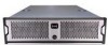
Appendix F Hardware Enclosures This appendix shows samples of hardware enclosures for the xStack Storage. F.1 Front View F.2 Back View Figure F- 1 Front View of Enclosure Figure F- 2 Rear View of Enclosure xStack Storage User's Guide 163 - D-Link DSN-3400-10 | User's Manual for DSN-3200-10
Valid for firmware 1.6.1 - Page 164
164 Appendix F Hardware Enclosures - D-Link DSN-3400-10 | User's Manual for DSN-3200-10
Valid for firmware 1.6.1 - Page 165
. The current version of IP is IPv4. Internet Small Computer System Interface. An IP-based standard for linking data storage devices over a network and transferring data by carrying SCSI commands over IP networks. iSCSI supports a Gigabit Ethernet interface at the physical layer that allows systems - D-Link DSN-3400-10 | User's Manual for DSN-3200-10
Valid for firmware 1.6.1 - Page 166
processing on the xStack Storage. A computer or other device, such as a printer. Every node has a unique network address, sometimes called a Data Link Control (DLC) address or Media Access Control (MAC) address. A way to improve reliability of a volume by providing data redundancy. In a parity - D-Link DSN-3400-10 | User's Manual for DSN-3200-10
Valid for firmware 1.6.1 - Page 167
devices whose IP addresses have the same prefix. For example, all devices with IP addresses that start with 100.100.100. are part of the same subnet. Transmission Control Protocol. Pronounced as separate letters, TCP is a or for a volume to span more than one disk. xStack Storage User's Guide 167 - D-Link DSN-3400-10 | User's Manual for DSN-3200-10
Valid for firmware 1.6.1 - Page 168
168 Appendix G Acronyms and Abbreviations
-
 1
1 -
 2
2 -
 3
3 -
 4
4 -
 5
5 -
 6
6 -
 7
7 -
8
-
9
-
10
-
11
-
12
-
13
-
14
-
15
-
16
-
17
-
18
-
19
-
20
-
21
-
22
-
23
-
24
-
25
-
26
-
27
-
28
-
29
-
30
-
31
-
32
-
33
-
34
-
35
-
36
-
37
-
38
-
39
-
40
-
41
-
42
-
43
-
44
-
45
-
46
-
47
-
48
-
49
-
50
-
51
-
52
-
53
-
54
-
55
-
56
-
57
-
58
-
59
-
60
-
61
-
62
-
63
-
64
-
65
-
66
-
67
-
68
-
69
-
70
-
71
-
72
-
73
-
74
-
75
-
76
-
77
-
78
-
79
-
80
-
81
-
82
-
83
-
84
-
85
-
86
-
87
-
88
-
89
-
90
-
91
-
92
-
93
-
94
-
95
-
96
-
97
-
98
-
99
-
100
-
101
-
102
-
103
-
104
-
105
-
106
-
107
-
108
-
109
-
110
-
111
-
112
-
113
-
114
-
115
-
116
-
117
-
118
-
119
-
120
-
121
-
122
-
123
-
124
-
125
-
126
-
127
-
128
-
129
-
130
-
131
-
132
-
133
-
134
-
135
-
136
-
137
-
138
-
139
-
140
-
141
-
142
-
143
-
144
-
145
-
146
-
147
-
148
-
149
-
150
-
151
-
152
-
153
-
154
-
155
-
156
-
157
-
158
-
159
-
160
-
161
-
162
-
163
-
164
-
165
-
166
-
167
-
168
 |
 |
xStack Storage
TM
D-Link xStack Storage iSCSI SAN Arrays
Managed SAN Solutions
DSN-3200 & DSN-3400
User’s Guide
Version 2.0