D-Link DSN-3400-10 User's Manual for DSN-3200-10 Valid for firmware 1.6.1 - Page 158
Replacing a Power Supply
 |
UPC - 790069299766
View all D-Link DSN-3400-10 manuals
Add to My Manuals
Save this manual to your list of manuals |
Page 158 highlights
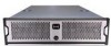
D.5 Replacing a Power Supply The xStack Storage Array contains three user replaceable power supply modules. They can be replaced as follows. 1. Locate the failed power supply module. Unscrew the bolt holding the locking mechanism in place as shown in Figure D-19. Figure D-19 Unscrew the Bolt Holding the Locking Mechanism 2. Push the locking lever to the left and pull on the handle as shown in Figure D-20. Figure D-20 Push the Locking Lever to the Left and Pull Handle 158 Appendix D Replacing and Upgrading FRUs
-
 1
1 -
2
-
3
-
4
-
5
-
6
-
7
-
8
-
9
-
10
-
11
-
12
-
13
-
14
-
15
-
16
-
17
-
18
-
19
-
20
-
21
-
22
-
23
-
24
-
25
-
26
-
27
-
28
-
29
-
30
-
31
-
32
-
33
-
34
-
35
-
36
-
37
-
38
-
39
-
40
-
41
-
42
-
43
-
44
-
45
-
46
-
47
-
48
-
49
-
50
-
51
-
52
-
53
-
54
-
55
-
56
-
57
-
58
-
59
-
60
-
61
-
62
-
63
-
64
-
65
-
66
-
67
-
68
-
69
-
70
-
71
-
72
-
73
-
74
-
75
-
76
-
77
-
78
-
79
-
80
-
81
-
82
-
83
-
84
-
85
-
86
-
87
-
88
-
89
-
90
-
91
-
92
-
93
-
94
-
95
-
96
-
97
-
98
-
99
-
100
-
101
-
102
-
103
-
104
-
105
-
106
-
107
-
108
-
109
-
110
-
111
-
112
-
113
-
114
-
115
-
116
-
117
-
118
-
119
-
120
-
121
-
122
-
123
-
124
-
125
-
126
-
127
-
128
-
129
-
130
-
131
-
132
-
133
-
134
-
135
-
136
-
137
-
138
-
139
-
140
-
141
-
142
-
143
-
144
-
145
-
146
-
147
-
148
-
149
-
150
-
151
-
152
-
 153
153 -
 154
154 -
 155
155 -
 156
156 -
 157
157 -
 158
158 -
 159
159 -
 160
160 -
 161
161 -
 162
162 -
 163
163 -
164
-
165
-
166
-
167
-
168
 |
 |

158
Appendix D
Replacing and Upgrading FRUs
D.5
Replacing a Power Supply
The xStack Storage Array contains three user replaceable power supply modules.
They can be
replaced as follows.
1.
Locate the failed power supply module.
Unscrew the bolt holding the locking mechanism in
place as shown in Figure D-19.
Figure D-19
Unscrew the Bolt Holding the Locking Mechanism
2.
Push the locking lever to the left and pull on the handle as shown in Figure D-20.
Figure D-20
Push the Locking Lever to the Left and Pull Handle