D-Link DSN-3400-10 User's Manual for DSN-3200-10 Valid for firmware 1.6.1 - Page 25
DSN-3400 External Interfaces, 2.2.4, DSN-3400 LEDs
 |
UPC - 790069299766
View all D-Link DSN-3400-10 manuals
Add to My Manuals
Save this manual to your list of manuals |
Page 25 highlights
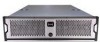
2.2.2.3 DSN-3400 External Interfaces The back of the xStack DSN-3400 enclosure provides the following external interfaces: A single 10 GbE XFP transceiver host network connection o (optical or copper depending on what interface you install) One DB9 RS-232-C diagnostic port One RJ-45 Fast Ethernet management port Figure 2-10 shows the hardware components on the back of the xStack DSN-3400. Figure 2-10 External Interfaces on the xStack DSN-3400 Enclosure 2.2.2.4 DSN-3400 LEDs Two LEDs next to the XFP connector show transmit (Tx) and receive (Rx) activity on the host network interface. Table 2-5 describes the Tx and Rx LED indicators on the back of the xStack DSN-3400 enclosure. Table 2-5 Host Network Connection LED Indicators on the xStack DSN-3400 Enclosure LED Tx Link Rx Link Color OFF Blinks Green OFF Solid Yellow Blinks Yellow Description There is no transmit activity. There is transmit activity from the xStack DSN-3400. There is no receive activity. A 10GbE connection has been established. There is receive activity with the xStack DSN-3400. xStack Storage User's Guide 25
-
 1
1 -
2
-
3
-
4
-
5
-
6
-
7
-
8
-
9
-
10
-
11
-
12
-
13
-
14
-
15
-
16
-
17
-
18
-
19
-
 20
20 -
 21
21 -
 22
22 -
 23
23 -
 24
24 -
 25
25 -
 26
26 -
 27
27 -
 28
28 -
 29
29 -
 30
30 -
31
-
32
-
33
-
34
-
35
-
36
-
37
-
38
-
39
-
40
-
41
-
42
-
43
-
44
-
45
-
46
-
47
-
48
-
49
-
50
-
51
-
52
-
53
-
54
-
55
-
56
-
57
-
58
-
59
-
60
-
61
-
62
-
63
-
64
-
65
-
66
-
67
-
68
-
69
-
70
-
71
-
72
-
73
-
74
-
75
-
76
-
77
-
78
-
79
-
80
-
81
-
82
-
83
-
84
-
85
-
86
-
87
-
88
-
89
-
90
-
91
-
92
-
93
-
94
-
95
-
96
-
97
-
98
-
99
-
100
-
101
-
102
-
103
-
104
-
105
-
106
-
107
-
108
-
109
-
110
-
111
-
112
-
113
-
114
-
115
-
116
-
117
-
118
-
119
-
120
-
121
-
122
-
123
-
124
-
125
-
126
-
127
-
128
-
129
-
130
-
131
-
132
-
133
-
134
-
135
-
136
-
137
-
138
-
139
-
140
-
141
-
142
-
143
-
144
-
145
-
146
-
147
-
148
-
149
-
150
-
151
-
152
-
153
-
154
-
155
-
156
-
157
-
158
-
159
-
160
-
161
-
162
-
163
-
164
-
165
-
166
-
167
-
168
 |
 |
