Dell 1135N Service Manual - Page 6
Reference Information, System Diagram - software
 |
View all Dell 1135N manuals
Add to My Manuals
Save this manual to your list of manuals |
Page 6 highlights
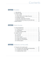
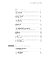
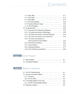
Contents 4.1.5 Menu Map 4-11 4.1.6 Tech Mode 4-12 4.1.7 EDC Mode 4-19 4.1.8 Firmware Upgrade 4-22 4.1.9 Periodic Defective Image 4-23 4.1.10 Error Message 4-24 4.2 Troubleshooting 4-28 4.2.1 Procedure of Checking the Symptoms 4-28 4.2.2 The cause and solution of Bad image 4-29 4.2.3 The cause and solution of the bad discharge 4-45 4.2.4 The cause and solution of the malfunction 4-52 4.2.5 The cause and solutions of bad environment of the software 4-61 4.2.6 Fax & Phone Problems 4-64 4.2.7 Copy Problems 4-73 4.2.8 Scanning Problems 4-77 4.2.9 Fuser Problems and solutions 4-80 chapter 5 System Diagram 5.1 Block Diagram 5-1 5.2 Connection Diagram 5-2 chapter 6 Reference Information 6.1 Tool for Troubleshooting 6-1 6.2 Acronyms and Abbreviations 6-2 6.2.1 Acronyms 6-2 6.2.2 Service Parts 6-4 6.3 The Sample Pattern for the Test 6-8 6.3.1 A4 ISO 19752 Standard Pattern 6-8 6.4 Selecting a location 6-9
-
 1
1 -
 2
2 -
 3
3 -
 4
4 -
 5
5 -
 6
6 -
 7
7 -
 8
8 -
 9
9 -
 10
10 -
 11
11 -
 12
12 -
13
-
14
-
15
-
16
-
17
-
18
-
19
-
20
-
21
-
22
-
23
-
24
-
25
-
26
-
27
-
28
-
29
-
30
-
31
-
32
-
33
-
34
-
35
-
36
-
37
-
38
-
39
-
40
-
41
-
42
-
43
-
44
-
45
-
46
-
47
-
48
-
49
-
50
-
51
-
52
-
53
-
54
-
55
-
56
-
57
-
58
-
59
-
60
-
61
-
62
-
63
-
64
-
65
-
66
-
67
-
68
-
69
-
70
-
71
-
72
-
73
-
74
-
75
-
76
-
77
-
78
-
79
-
80
-
81
-
82
-
83
-
84
-
85
-
86
-
87
-
88
-
89
-
90
-
91
-
92
-
93
-
94
-
95
-
96
-
97
-
98
-
99
-
100
-
101
-
102
-
103
-
104
-
105
-
106
-
107
-
108
-
109
-
110
-
111
-
112
-
113
-
114
-
115
-
116
-
117
-
118
-
119
-
120
-
121
-
122
-
123
-
124
-
125
-
126
-
127
-
128
-
129
-
130
-
131
-
132
-
133
-
134
-
135
-
136
-
137
-
138
-
139
-
140
-
141
-
142
-
143
-
144
-
145
-
146
-
147
-
148
-
149
-
150
-
151
-
152
-
153
-
154
-
155
-
156
-
157
-
158
-
159
-
160
-
161
-
162
-
163
-
164
-
165
-
166
-
167
-
168
-
169
 |
 |
