Dell Alienware x16 R2 Owners Manual - Page 68
Display assembly, Removing the display assembly
 |
View all Dell Alienware x16 R2 manuals
Add to My Manuals
Save this manual to your list of manuals |
Page 68 highlights
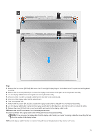
6. Slide the touchpad-light cable into the connector on the keyboard-controller board and close the latch to secure the cable. NOTE: Your computer may be shipped with a touchpad-light cable depending on the configuration you have ordered. 7. Slide the keyboard-backlight cable into the connector on the keyboard-controller board and close the latch to secure the cable. 8. Place the Mylar that secures the keyboard-controller board to the palm-rest and keyboard assembly. NOTE: For models shipped with a per-key or mechanical keyboard, the computer will require a keyboard language and keyboard color setup after keyboard-controller board is replaced. When the computer is reassembled and turned on, an error message is displayed. Press F2 to go to the Keyboard section of the BIOS Setup Utility to set up the keyboard language and keyboard color. See the bundled Tech Sheet for details on configuring the keyboard language. Next steps 1. Install the battery. 2. Install the base cover. 3. Follow the procedure in After working inside your computer. Display assembly Removing the display assembly CAUTION: The information in this removal section is intended for authorized service technicians only. Prerequisites 1. Follow the procedure in Before working inside your computer. 2. Remove the base cover. 3. Remove the rear I/O-cover. About this task NOTE: The display assembly is a Hinge-Up Display (HUD) and cannot be further disassembled. The following images indicate the location of the display assembly and provide a visual representation of the removal procedure. 68
-
 1
1 -
2
-
3
-
4
-
5
-
6
-
7
-
8
-
9
-
10
-
11
-
12
-
13
-
14
-
15
-
16
-
17
-
18
-
19
-
20
-
21
-
22
-
23
-
24
-
25
-
26
-
27
-
28
-
29
-
30
-
31
-
32
-
33
-
34
-
35
-
36
-
37
-
38
-
39
-
40
-
41
-
42
-
43
-
44
-
45
-
46
-
47
-
48
-
49
-
50
-
51
-
52
-
53
-
54
-
55
-
56
-
57
-
58
-
59
-
60
-
61
-
62
-
 63
63 -
 64
64 -
 65
65 -
 66
66 -
 67
67 -
 68
68 -
 69
69 -
 70
70 -
 71
71 -
 72
72 -
 73
73 -
74
-
75
-
76
-
77
-
78
-
79
-
80
-
81
-
82
-
83
-
84
-
85
-
86
-
87
-
88
-
89
-
90
-
91
-
92
-
93
-
94
-
95
-
96
-
97
-
98
-
99
-
100
-
101
-
102
-
103
-
104
-
105
-
106
-
107
-
108
-
109
-
110
-
111
-
112
-
113
-
114
-
115
-
116
-
117
-
118
-
119
-
120
-
121
-
122
-
123
-
124
-
125
-
126
-
127
-
128
-
129
-
130
-
131
-
132
-
133
 |
 |
