Dell Alienware x16 R2 Owners Manual - Page 84
System board, Removing the system board
 |
View all Dell Alienware x16 R2 manuals
Add to My Manuals
Save this manual to your list of manuals |
Page 84 highlights
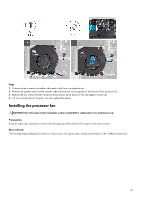
Steps 1. Align and place the power-adapter port into the slot on the palm-rest and keyboard assembly. 2. Connect the power-adapter port cable to the system board. 3. Adhere the tape that secures the power-adapter port to the fan and heat-sink assembly. 4. Route the power-adapter port cable through the routing guides on the fan and heat-sink assembly. 5. Place the power-adapter port bracket on the power-adapter port. 6. Align the screw holes on the power-adapter port bracket with the screw holes on the palm-rest and keyboard assembly. 7. Replace the two screws (M2x2.5) that secure the power-adapter port bracket to the palm-rest and keyboard assembly. Next steps 1. Install the rear I/O-cover. 2. Install the base cover. 3. Follow the procedure in After working inside your computer. System board Removing the system board CAUTION: The information in this removal section is intended for authorized service technicians only. Prerequisites 1. Follow the procedure in Before working inside your computer. 2. Remove the base cover. 3. Remove the battery. 4. Remove the wireless card. 5. Remove the M.2 2230 solid state drive or M.2 2280 solid state drive, as applicable. 6. Remove the solid state drive bracket. 7. Remove the processor fan. 8. Remove the graphics-card fan. 84
-
 1
1 -
2
-
3
-
4
-
5
-
6
-
7
-
8
-
9
-
10
-
11
-
12
-
13
-
14
-
15
-
16
-
17
-
18
-
19
-
20
-
21
-
22
-
23
-
24
-
25
-
26
-
27
-
28
-
29
-
30
-
31
-
32
-
33
-
34
-
35
-
36
-
37
-
38
-
39
-
40
-
41
-
42
-
43
-
44
-
45
-
46
-
47
-
48
-
49
-
50
-
51
-
52
-
53
-
54
-
55
-
56
-
57
-
58
-
59
-
60
-
61
-
62
-
63
-
64
-
65
-
66
-
67
-
68
-
69
-
70
-
71
-
72
-
73
-
74
-
75
-
76
-
77
-
78
-
 79
79 -
 80
80 -
 81
81 -
 82
82 -
 83
83 -
 84
84 -
 85
85 -
 86
86 -
 87
87 -
 88
88 -
 89
89 -
90
-
91
-
92
-
93
-
94
-
95
-
96
-
97
-
98
-
99
-
100
-
101
-
102
-
103
-
104
-
105
-
106
-
107
-
108
-
109
-
110
-
111
-
112
-
113
-
114
-
115
-
116
-
117
-
118
-
119
-
120
-
121
-
122
-
123
-
124
-
125
-
126
-
127
-
128
-
129
-
130
-
131
-
132
-
133
 |
 |
