Dell Force10 E600i E600i System Installation Guide - Page 11
Grounding, Holes, Fan Tray, E600i Chassis Rear View, Table 2-1.
 |
View all Dell Force10 E600i manuals
Add to My Manuals
Save this manual to your list of manuals |
Page 11 highlights
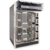
Figure 2-2. E600i Chassis Rear View Fan Tray Table 2-1. E600i System Component Requirements Component Backplane (factory installed) Air filter (factory installed) Fan tray RPMs Line cards SFMs Power Supplies: 2500 AC Power Supply OR DC PEMs Minimum 1 1 1 1 1 4 2 1 Maximum 1 1 1 2 7 5 4 2 Field-Replaceable N Y Y Y Y Y Y Y Grounding Holes The E600i System | 11
-
 1
1 -
2
-
3
-
4
-
5
-
 6
6 -
 7
7 -
 8
8 -
 9
9 -
 10
10 -
 11
11 -
 12
12 -
 13
13 -
 14
14 -
 15
15 -
 16
16 -
17
-
18
-
19
-
20
-
21
-
22
-
23
-
24
-
25
-
26
-
27
-
28
-
29
-
30
-
31
-
32
-
33
-
34
-
35
-
36
-
37
-
38
-
39
-
40
-
41
-
42
-
43
-
44
-
45
-
46
-
47
-
48
-
49
-
50
-
51
-
52
-
53
-
54
-
55
-
56
-
57
-
58
-
59
-
60
-
61
-
62
-
63
-
64
-
65
-
66
-
67
-
68
 |
 |

The E600i System
|
11
Figure 2-2.
E600i Chassis Rear View
Table 2-1.
E600i System Component Requirements
Component
Minimum
Maximum
Field-Replaceable
Backplane (factory installed)
1
1
N
Air filter (factory installed)
1
1
Y
Fan tray
1
1
Y
RPMs
1
2
Y
Line cards
1
7
Y
SFMs
4
5
Y
Power Supplies:
2500 AC Power Supply OR
DC PEMs
2
1
4
2
Y
Y
Grounding
Holes
Fan Tray