Dell Force10 S25-01-GE-24P Installing the S25P System
Dell Force10 S25-01-GE-24P Manual
 |
View all Dell Force10 S25-01-GE-24P manuals
Add to My Manuals
Save this manual to your list of manuals |
Dell Force10 S25-01-GE-24P manual content summary:
- Dell Force10 S25-01-GE-24P | Installing the S25P System - Page 1
Installing the S25P System December 15, 2008 100-00058-02 - Dell Force10 S25-01-GE-24P | Installing the S25P System - Page 2
of Conditions In the interest of improving internal design, operational function, and/or reliability, Force10 Networks reserves the right to make changes to products described in this document without notice. Force10 Networks does not assume any liability that may occur due to the use or application - Dell Force10 S25-01-GE-24P | Installing the S25P System - Page 3
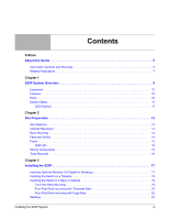
Contents Preface About this Guide 5 Information Symbols and Warnings 5 Related Publications 7 Chapter 1 S25P 13 Cabinet Placement 14 Rack Mounting 14 Fans and Airflow 14 Power 15 S25P-DC 15 Storing Components 15 Tools Required 16 Chapter 3 Installing the S25P 17 Inserting Optional - Dell Force10 S25-01-GE-24P | Installing the S25P System - Page 4
Commands 25 Connecting Stack Ports (optional 25 Supplying Power 27 S25P-DC 28 Chapter 4 Installing Ports 29 Accessing the Console Port 29 Installing Disposal 36 Appendix A Technical Support 39 The iSupport Website 39 Accessing iSupport Services 40 Contacting the Technical Assistance - Dell Force10 S25-01-GE-24P | Installing the S25P System - Page 5
Guide This guide S25P, refer to the SFTOS™ Configuration Guide for software configuration information and the SFTOS™ Table 1 describes symbols contained in this guide. Table 1 Information Symbols Symbol Warning and qualified personnel only. Read this guide before installing and powering up this - Dell Force10 S25-01-GE-24P | Installing the S25P System - Page 6
Leitern) verwendet wird. Warning: Building Supply Notice for DC Power Supply Use An external disconnect must be provided and be easily accessible. Force10 Networks recommends the use of a 60A circuit breaker. and regulations. See Product Recycling and Disposal on page 45. 6 About this Guide - Dell Force10 S25-01-GE-24P | Installing the S25P System - Page 7
rebut les batteries usagees conformement aux instructions du fabricant. Note: Other cautionary guides and the FTOS and SFTOS files listed above, respectively, except for the Release Notes. The CD-ROMs also have: • MIBs: Files for all SNMP MIBs supported by the software • Data sheets: Links to Force10 - Dell Force10 S25-01-GE-24P | Installing the S25P System - Page 8
.force10networks.com/CSPortal20/Main/SupportMain.aspx The iSupport website also has a section for S-Series techtips and FAQs. For more information in this book on technical support, see Technical Support on page 39. 8 About this Guide - Dell Force10 S25-01-GE-24P | Installing the S25P System - Page 9
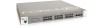
Overview The Force10 Networks S25P (Cat# S25-01-GE-24P) is a high performance, low cost, stackable, Layer 2 switch/Layer 3 router that supports 24 SFP The LEDs labeled AC1 and AC2 are DC1 and DC2 on the S25P-DC (cat.# S25-01-GE-24P-DC). Figure 2 The S25P (Rear View) Label (Part #, Serial #, - Dell Force10 S25-01-GE-24P | Installing the S25P System - Page 10
source to the S25P (power cables are not supplied for the S25P-DC) • Bracket ears for rack installation (supplied) • Screws for rack installation entries supported with hardware-assisted aging • Supports 9252-byte jumbo frames in FTOS, 9216-byte jumbo frames in SFTOS • Back-pressure support at half - Dell Force10 S25-01-GE-24P | Installing the S25P System - Page 11
menu options, both discussed here, along with CLI show commands,and SNMP traps. For details on those options, see the Command Reference and Configuration Guide for your software (FTOS or SFTOS). LED Displays As shown in Figure 1, the S25P front panel contains several sets of LEDs: • Stack ID: This - Dell Force10 S25-01-GE-24P | Installing the S25P System - Page 12
The following table describes the LED status indicators on the left side of the front panel. Table 4 Status Panel LED Display Label LED Color Description Left Side of the Status Panel Green Unit is online. Blinking Green Unit is booting up (blinking rate is 16 Hz). OK Amber Error during - Dell Force10 S25-01-GE-24P | Installing the S25P System - Page 13
Chapter 2 Site Preparation This chapter describes requirements and procedures to install your S25P system, in the following topics: • Site Selection • Cabinet Placement on page 14 • Rack Mounting on page 14 • Fans and Airflow on page 14 • Power on page 15 • Storing Components on page 15 • Tools - Dell Force10 S25-01-GE-24P | Installing the S25P System - Page 14
rack must be grounded to the same ground point used by the power service in your area. The ground path must be permanent. Fans and Airflow see the System Logs chapters of the SFTOS Command Reference and SFTOS Configuration Guide. In a stack, each unit has its own temperature monitoring and control - Dell Force10 S25-01-GE-24P | Installing the S25P System - Page 15
28, Right to Left Ground Connector DC1 Figure 4 The S50N-DC Rear View For details on connecting to a power source, see Supplying Power on page 27. Storing Components If you do not install your system and components immediately, Force10 Networks recommends that you properly store the S25P and all - Dell Force10 S25-01-GE-24P | Installing the S25P System - Page 16
the packing tape, and a Philips #2 screwdriver is required for attaching rack screws, and is also used for making some attachments, including DC cables and rear cover plates. Warning: Electrostatic discharge (ESD) damage can occur when components are mishandled. Always wear an ESD-preventive wrist - Dell Force10 S25-01-GE-24P | Installing the S25P System - Page 17
system, Force10 Networks recommends on page 24 • Supplying Power on page 27 - S25P-DC on page 28 Warning: As with all electrical devices of or Stacking) The S25P (catalog name S25-01-GE-24P) has two expansion slots in the S50-01-10GE-2P S50-01-10GE-2C S50-01-12G-2S S50-01-24G-1S The system supports - Dell Force10 S25-01-GE-24P | Installing the S25P System - Page 18
installation instructions that come with the transceiver). The CX4 module (catalog name S50-01- 10GE-2C) ports do not require inserts. Caution: You can connect a CX4 cable to an XFP port through a CX4 XFP converter (catalog number GP- XFP-1CX4) in the slot. However, an XFP port does not support - Dell Force10 S25-01-GE-24P | Installing the S25P System - Page 19
screws through each bracket and onto the rack post. Figure 6 S25P Two-post (Front-mounted) Rack-mounting Stack ID AC1 XFP25 XFP26 AACla2rm 27 P28 S25-01-GE-24P Installing the S25P System 19 - Dell Force10 S25-01-GE-24P | Installing the S25P System - Page 20
, and secure the mounting bracket with three screws. Figure 7 Four-Post Rack-mounting with Threaded Rails Stack ID AC1 XFP25 XFP26 AACla2rm 27 P28 S25-01-GE-24P 2 Insert the S25P into the rack, and secure the chassis to the front post with two screws. Then secure the chassis to the rear - Dell Force10 S25-01-GE-24P | Installing the S25P System - Page 21
your bracket. Secure the length with the four screws. Figure 9 Four-post Rack-mounting with Threaded Rails . Stack ID AC1 XFP25 XFP26 AACla2rm 27 P28 S25-01-GE-24P fn00146cs25P.eps Installing the S25P System 21 - Dell Force10 S25-01-GE-24P | Installing the S25P System - Page 22
using the screws. Figure 10 Four-Post Rack-mounting with Cage Nuts Top View of Brackets Stack ID AC1 XFP25 XFP26 AACla2rm 27 P28 S25-01-GE-24P Align brackets fn00147f_s25P 2 Align and secure the adjustable bracket onto the rear bracket. 3 Insert the S25P chassis into the rear of the rack - Dell Force10 S25-01-GE-24P | Installing the S25P System - Page 23
each bracket flange and each rack post. Figure 12 Four-Post Rack-mounting with Cage Nuts fn00147d_s25P Stack ID AC1 XFP25 XFP26 AACla2rm 27 P28 S25-01-GE-24P 5 Align the rack filler panel to the rear bracket and rack posts. Secure by inserting two screws into the hole in the filler panel - Dell Force10 S25-01-GE-24P | Installing the S25P System - Page 24
online. So, when setting up a new stack, you should have no trouble forcing the identification of the management unit and unit IDs by methodically supplying power Stacking chapters of the SFTOS Command Reference and the SFTOS Configuration Guide. You can execute clear config on the switch to start - Dell Force10 S25-01-GE-24P | Installing the S25P System - Page 25
Command Reference and the S-Series Stacking chapter in the FTOS Configuration Guide. Connecting Stack Ports (optional) The S25P contains two expansion slots see Figure 14). Use the special stacking cables to connect them. Force10 recommends that you mount the switches before you make your stack port - Dell Force10 S25-01-GE-24P | Installing the S25P System - Page 26
Figure 16 Stack Ports of Two S25P Switches Connected in a Ring fn00151s25P-1 STACK STACK STACK STACK Stack Port A Stack Port B Note: These diagrams and instructions use "Stack Port A" and "Stack Port B" for clarifying the connections, but the modules are not labeled. 26 Installing the S25P - Dell Force10 S25-01-GE-24P | Installing the S25P System - Page 27
Connecting Three Switches Force10 recommends the ring topology, as outlined above (Figure 14 on page 25), for stacking S-Series switches, providing redundant connectivity. Using the example of three switches - Dell Force10 S25-01-GE-24P | Installing the S25P System - Page 28
separate circuits. S25P-DC As shown below (see also Figure 4 on page 15), the S25P-DC (cat. name S25-01-GE-24P-DC) has two DC terminal blocks on the connect to the power source. Cables must be sized for 11.5 A service at -48VDC input (per NEC in the United States. Internationally, follow local - Dell Force10 S25-01-GE-24P | Installing the S25P System - Page 29
Chapter 4 Installing Ports This chapter contains these major sections: • Accessing the Console Port • Installing Optics on page 30 - Installing SFPs on page 31 - Installing XFPs on page 32 Accessing the Console Port Connect the RJ-45/DB-9 adapter that is shipped with the S25P system to the RJ-45 - Dell Force10 S25-01-GE-24P | Installing the S25P System - Page 30
SFTOS, see the Getting Started chapter of the SFTOS Configuration Guide for other console port details, such as setting the console timeout the receive power of the transceiver with an optical power meter. Generally, Force10 specified optics are not to be subjected to receive power higher than - Dell Force10 S25-01-GE-24P | Installing the S25P System - Page 31
SFP2 module with catalog number GP-SFP2-1T is used in the S25P switch, the SFP speed can be manually set with the speed command. When the speed is set to 10 or 100 Mbps, the duplex command into place. Figure 19 Front View of S25P with SFP S25-01-GE-24P fn00161s25P Installing the S25P System 31 - Dell Force10 S25-01-GE-24P | Installing the S25P System - Page 32
converter (catalog name GP- XFP-1CX4) into the slot. An XFP port does not support the use of the cx4-cable-length command. For details, see Inserting Optional Modules see the FTOS Configuration Guide. With SFTOS, see the SFTOS Configuration Guide or the S50V and S50N Quick Reference. 32 - Dell Force10 S25-01-GE-24P | Installing the S25P System - Page 33
32° to 122°F (0° to 50°C) • Non-operating (storage temperature): -40° to 158°F (-40° to 70°C) Maximum Thermal Output S25P: 305 BTU/Hour S25P-DC: 262 BTU/Hour Maximum altitude No performance degradation to 10,000 feet (3,048 meters) Relative humidity 10 to 85% non-condensing (operating) 5 to 95 - Dell Force10 S25-01-GE-24P | Installing the S25P System - Page 34
DC: 3.6 A @ -48 VDC .25 A @ 254 VAC .56 A @ 90 VAC S25P: 90W S25P-DC: 77W Note: S25P and S25P-DC switches contain a lithium battery. The switch contains no user-serviceable used in accordance to the instructions, it may cause harmful meet FCC emission limits. Force10 Networks is not responsible for - Dell Force10 S25-01-GE-24P | Installing the S25P System - Page 35
used in a domestic environment, radio disturbance may arise. When such trouble occurs, the user may be required to take corrective actions. Danger: AC Power cords are for use with Force10 Networks equipment only. Do not use Force10 Networks AC power cords with any unauthorized hardware. Korea (MIC - Dell Force10 S25-01-GE-24P | Installing the S25P System - Page 36
EN 60825-1 Safety of Laser Products-Part 1: Equipment Classification Requirements and User's Guide • EN 60825-2 Safety of Laser Products-Part 2: Safety of Optical Fibre it is no longer needed. Force10 offers a variety of product return programs and services in several countries to assist equipment - Dell Force10 S25-01-GE-24P | Installing the S25P System - Page 37
, as required by WEEE. For information on Force10 product recycling offerings, see the WEEE Recycling instructions on iSupport at: https://www.force10networks.com/CSPortal20/Support/WEEEandRecycling.pdf. For more information, contact the Force10 Technical Assistance Center (TAC) (see Contacting the - Dell Force10 S25-01-GE-24P | Installing the S25P System - Page 38
the environment and human health due to the potential presence of hazardous substances. For proper collection and treatment, contact your local Force10 Networks representative. Figure 22 The European WEEE symbol For California: Perchlorate Material - Special handling may apply. See: http://www.dtsc - Dell Force10 S25-01-GE-24P | Installing the S25P System - Page 39
Center (TAC) cases. Force10 iSupport provides integrated, secure access to these services. The i-Support website (see Figure 24, below) (http://www.force10networks.com/support/) contains a publicly available interface that includes access to techtips, white papers, and user manuals. After you get an - Dell Force10 S25-01-GE-24P | Installing the S25P System - Page 40
The screenshot above shows the Support Policies section of iSupport. The Support Guide, available on that page, details the types of information and services that you can access through iSupport and through various types of support contracts. Accessing iSupport Services The URL for iSupport is - Dell Force10 S25-01-GE-24P | Installing the S25P System - Page 41
Assistance Center How to Contact Force10 TAC Information to Submit When Opening a Support Case Managing Your Case Downloading Software Updates Technical Documentation Contact Information Log in to iSupport at http://www.force10networks.com/support/, and select the Service Request tab. • Your name - Dell Force10 S25-01-GE-24P | Installing the S25P System - Page 42
Locating Serial Numbers You can use the show switch unit command in the CLI to access the serial number of the designated switch (unit = stack ID). The serial number of the chassis is located on a sticker on the back of the chassis in the middle. The serial number is below the bar code and has 11 - Dell Force10 S25-01-GE-24P | Installing the S25P System - Page 43
support case. Open a support case by: • Using the Create Service Request form on the iSupport page (see Contacting the Technical Assistance Center, above). • Contacting Force10 show tech-support.) • Console captures showing the error messages • Console captures showing the troubleshooting steps taken - Dell Force10 S25-01-GE-24P | Installing the S25P System - Page 44
44 - Dell Force10 S25-01-GE-24P | Installing the S25P System - Page 45
14 altitude, maximum 33 B back-pressure support 10 bar code 9 battery removal 37 battery, lithium 34 baud rate 29 brackets 10 C Cabinet placement 14 catalog name 9 catalog name GP- XFP-1CX4 (for CX4 XFP) 18, 32 catalog name S25-01-GE-24P (S25P switch) 9 catalog name S50-01-10GE-2C (CX4 module) 18 - Dell Force10 S25-01-GE-24P | Installing the S25P System - Page 46
D Danger 5, 6 DB-9 to RJ-45 10 DC Power Supply 6 DC1 9 DC2 9 depth of chassis 33 disposal, switch 36 13, 33 I Immunity 36 46 Installation Cabinet 19 Rack 19 Tabletop 19 iSupport 40 J jumbo frame support 10 jumbo frames 10 L LED Displays 11 LEDs, port status 11 LEDs, stacking 11 LEDs, Status - Dell Force10 S25-01-GE-24P | Installing the S25P System - Page 47
29 S S25-01-GE-48P (S25P catalog name) 17 S25P front view 9 S25P rear view 9 S25P status information 11 S25P switch catalog name 9 S25P-DC 9 S50V show system stack-unit command 25 show tech command 43 show tech-support command 43 SNMP traps 11 sound levels 33 Specifications Agency Compliance 34 - Dell Force10 S25-01-GE-24P | Installing the S25P System - Page 48
settings, console 30 Thermal Output, Maximum 33 Tools Required 16 topology cascade 25 ring 25 V ventilation 14 Vibration 33 voltage 34 W Warning 6 AC Power Supply 6 DC Power Supply 6 WEEE 37, 38 Weight 33 width of chassis 33 X XFP Installation 32 XFP LINK/ACT 9, 15 XFP Port LED 11 XFP ports 10
-
 1
1 -
 2
2 -
 3
3 -
 4
4 -
 5
5 -
 6
6 -
 7
7 -
8
-
9
-
10
-
11
-
12
-
13
-
14
-
15
-
16
-
17
-
18
-
19
-
20
-
21
-
22
-
23
-
24
-
25
-
26
-
27
-
28
-
29
-
30
-
31
-
32
-
33
-
34
-
35
-
36
-
37
-
38
-
39
-
40
-
41
-
42
-
43
-
44
-
45
-
46
-
47
-
48
 |
 |
Installing the S25P System
December 15, 2008
100-00058-02