Dell Force10 S25-01-GE-24P Installing the S25P System - Page 26
Connecting Two Switches, Switch 1, Module A, Ring topology, using two, 24Gig modules
 |
View all Dell Force10 S25-01-GE-24P manuals
Add to My Manuals
Save this manual to your list of manuals |
Page 26 highlights
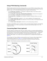
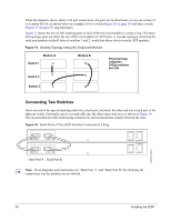
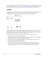
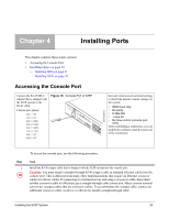
While the diagram, above, shows A-B port connections, the ports are bi-directional, so you can connect A to A and/or B to B, as shown below in examples of two-switch (Figure 16 on page 26) and three-switch (Figure 17 on page 27) ring topologies. Figure 15 shows the use of 24G stacking ports in each of the two rear modules to create a ring. Of course, this topology does not allow the use of the rear modules for XFP ports. A cascade topology, removing the stack port modules in the B slots of switches 1 and 2, would free those slots for use by XFP modules. Figure 15 Stacking Topology Using 24G Single-port Modules Module A Switch 1 A A Switch 2 Module B B B Ring topology using two 24Gig modules per unit Switch 3 A B Connecting Two Switches Insert one end of the special stacking cable into a stack port, and insert the other end into a stack port of the adjacent switch. Optionally, insert a second cable into the other open stack port, as shown in Figure 14. The second cable provides both backup connectivity and increased data transfer between the units. Figure 16 Stack Ports of Two S25P Switches Connected in a Ring fn00151s25P-1 STACK STACK STACK STACK Stack Port A Stack Port B Note: These diagrams and instructions use "Stack Port A" and "Stack Port B" for clarifying the connections, but the modules are not labeled. 26 Installing the S25P
-
 1
1 -
2
-
3
-
4
-
5
-
6
-
7
-
8
-
9
-
10
-
11
-
12
-
13
-
14
-
15
-
16
-
17
-
18
-
19
-
20
-
 21
21 -
 22
22 -
 23
23 -
 24
24 -
 25
25 -
 26
26 -
 27
27 -
 28
28 -
 29
29 -
 30
30 -
 31
31 -
32
-
33
-
34
-
35
-
36
-
37
-
38
-
39
-
40
-
41
-
42
-
43
-
44
-
45
-
46
-
47
-
48
 |
 |
