Dell Force10 S25-01-GE-24P Installing the S25P System - Page 14
Cabinet Placement, Rack Mounting, Fans and Airflow, Environmental Parameters on Table 4
 |
View all Dell Force10 S25-01-GE-24P manuals
Add to My Manuals
Save this manual to your list of manuals |
Page 14 highlights
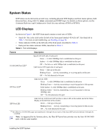
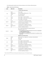
Cabinet Placement The cabinet must meet the following criteria: • Minimum cabinet size and airflow are according to the EIA standard. • Minimum of 5 inches (12.7 cm) between the side intake and exhaust vents and the cabinet wall. Rack Mounting When you prepare your equipment rack, ensure that the rack is earth ground. The equipment rack must be grounded to the same ground point used by the power service in your area. The ground path must be permanent. Fans and Airflow Ventilation is side-to-side, with six fans on the left side of the switch that operate at a constant speed. For proper ventilation, position the S25P chassis in an equipment rack (or cabinet) with a minimum of five inches (12.7 cm) of clearance around the side intake and exhaust vents. When two S25P systems are installed side by side, position the two S25P chassis at least 5 inches (12.7 cm) apart to permit proper airflow. The acceptable ambient temperature ranges are listed in Environmental Parameters on page 33. As listed in Table 4, "Status Panel LED Display," on page 12, the front panel of the S25P has an Alarm status LED, which is green when the switch is operating within required temperature parameters and all components are operating normally, including fans. The LED is amber when the temperature or components are outside expected parameters, red in a major alarm. SFTOS logs a temperature warning message when a temperature of 77 degrees C is reached, and logs another message when the temperature returns to normal. The Command Line Interface (CLI) also reports an alarm. Use the show logging command to see the log messages. For details, see the System Logs chapters of the SFTOS Command Reference and SFTOS Configuration Guide. In a stack, each unit has its own temperature monitoring and control. Status logging is identified by unit in the system log. Fan replacement in the field is not offered as an option. 14 Site Preparation
-
 1
1 -
2
-
3
-
4
-
5
-
6
-
7
-
8
-
 9
9 -
 10
10 -
 11
11 -
 12
12 -
 13
13 -
 14
14 -
 15
15 -
 16
16 -
 17
17 -
 18
18 -
 19
19 -
20
-
21
-
22
-
23
-
24
-
25
-
26
-
27
-
28
-
29
-
30
-
31
-
32
-
33
-
34
-
35
-
36
-
37
-
38
-
39
-
40
-
41
-
42
-
43
-
44
-
45
-
46
-
47
-
48
 |
 |