Dell Force10 S25-01-GE-24P Installing the S25P System - Page 29
Installing Ports, Accessing the Console Port
 |
View all Dell Force10 S25-01-GE-24P manuals
Add to My Manuals
Save this manual to your list of manuals |
Page 29 highlights
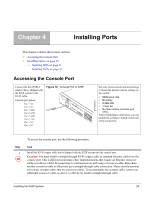
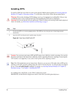
Chapter 4 Installing Ports This chapter contains these major sections: • Accessing the Console Port • Installing Optics on page 30 - Installing SFPs on page 31 - Installing XFPs on page 32 Accessing the Console Port Connect the RJ-45/DB-9 adapter that is shipped with the S25P system to the RJ-45 cable. Console port pinout: Pin 1 = NC Pin 2 = NC Pin 3 = RXD Pin 4 = GND Pin 5 = GND Pin 6 = TXD Pin 7 = NC Pin 8 = NC Figure 18 Console Port of S25P Stack ID AC1 XFP25 XFP26 AACla2rm 27 P28 fn00159s25P Set your initial console terminal settings to match the default console settings on the switch: • 9600 baud rate • No parity • 8 data bits • 1 stop bit • No flow control (console port only) After establishing a connection, you can modify the settings to match at each end of the connection. To access the console port, use the following procedure. Step Task 1 Install the RJ-45 copper cable that is shipped with the S25P system into the console port. Caution: You must install a straight-through RJ-45 copper cable (a standard Ethernet cable) into the console port. This is different from many other implementations that require an Ethernet crossover cable (or rollover cable). If connecting to a terminal server and using a crossover cable, daisychain another crossover cable to effectively get a straight-through cable connection. Many console terminal servers use octopus cables that are crossover cables. To accommodate the octopus cable, connect an additional crossover cable, as above, to effectively install a straight-through cable. Installing the S25P System 29
-
 1
1 -
2
-
3
-
4
-
5
-
6
-
7
-
8
-
9
-
10
-
11
-
12
-
13
-
14
-
15
-
16
-
17
-
18
-
19
-
20
-
21
-
22
-
23
-
 24
24 -
 25
25 -
 26
26 -
 27
27 -
 28
28 -
 29
29 -
 30
30 -
 31
31 -
 32
32 -
 33
33 -
 34
34 -
35
-
36
-
37
-
38
-
39
-
40
-
41
-
42
-
43
-
44
-
45
-
46
-
47
-
48
 |
 |
