Dell Force10 S25-01-GE-24P Installing the S25P System - Page 17
Installing the S25P, Inserting Optional Modules (10-Gigabit or Stacking)
 |
View all Dell Force10 S25-01-GE-24P manuals
Add to My Manuals
Save this manual to your list of manuals |
Page 17 highlights
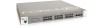
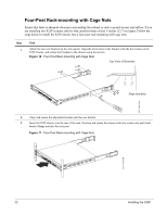
Chapter 3 Installing the S25P To install the S25P system, Force10 Networks recommends that you complete the installation procedures in the order presented in this chapter: • Inserting Optional Modules (10-Gigabit or Stacking) • Installing the Switch on a Tabletop on page 19 • Installing the Switch in a Rack or Cabinet on page 19 • Stacking on page 24 • Supplying Power on page 27 - S25P-DC on page 28 Warning: As with all electrical devices of this type, take all the necessary safety precautions to prevent injury when installing this system. Electrostatic discharge (ESD) damage can occur if components are mishandled. Always wear an ESD-preventive wrist or heel ground strap when handling the S25P and its components. Inserting Optional Modules (10-Gigabit or Stacking) The S25P (catalog name S25-01-GE-24P) has two expansion slots in the back of the chassis, for which there are four modules available: Module Description Catalog Name 2-port 10GbE XFP (optical connection) 2-port 10GbE CX4 (copper connection) 2-port 12GbE Stacking 1-port 24GbE Stacking S50-01-10GE-2P S50-01-10GE-2C S50-01-12G-2S S50-01-24G-1S The system supports inserting the modules in any combination of slots (although connecting all four ports of two 12G stacking modules is not supported, nor is connecting one kind of stack port to anything other than the same kind of stack port). The ports are numbered 25 through 28, from left to right as you face the front of the chassis. So, for clarity in the use of the CLI in port assignment, if you are only using one XFP or CX4 module, insert it in the left-most expansion slot. Note: The 10G modules cannot be used for stacking. See Connecting Stack Ports (optional) on page 25. Installing the S25P System 17
-
 1
1 -
2
-
3
-
4
-
5
-
6
-
7
-
8
-
9
-
10
-
11
-
 12
12 -
 13
13 -
 14
14 -
 15
15 -
 16
16 -
 17
17 -
 18
18 -
 19
19 -
 20
20 -
 21
21 -
 22
22 -
23
-
24
-
25
-
26
-
27
-
28
-
29
-
30
-
31
-
32
-
33
-
34
-
35
-
36
-
37
-
38
-
39
-
40
-
41
-
42
-
43
-
44
-
45
-
46
-
47
-
48
 |
 |
