Dell Force10 S25-01-GE-24P Installing the S25P System - Page 27
Connecting Three Switches, Supplying Power
 |
View all Dell Force10 S25-01-GE-24P manuals
Add to My Manuals
Save this manual to your list of manuals |
Page 27 highlights
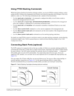
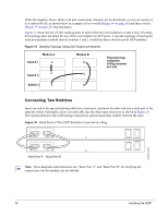
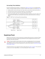
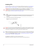
Connecting Three Switches Force10 recommends the ring topology, as outlined above (Figure 14 on page 25), for stacking S-Series switches, providing redundant connectivity. Using the example of three switches in the stack (Figure 16): 1 Starting with the switch at the bottom of the stack, insert one end of the first cable into Stack Port A. 2 Insert the other end of the first cable into Stack Port A of the middle switch. 3 Insert the second cable into Stack Port B of the middle and top switches. 4 Connect the remaining cable to the top and bottom switches by inserting one end of the cable into the open Stack Port B of the bottom switch and the other end of the cable into Stack Port A of the top switch. Figure 17 S25P Rear View Showing Ring Topology Stacking STACK STACK STACK STACK STACK Stack Port A STACK Stack Port B fn00152s50V1 Supplying Power Supply power to the units in a stack only after they are mounted and the stack ports are connected. There is no on/off switch, and the stack members partly determine the stack management unit from the order in which they come online (see below). Danger: To prevent electrical shock, make sure the switch is grounded properly. If you do not ground your equipment correctly, excessive emissions can result. Use a qualified electrician to ensure that the power cables meet your local electrical requirements. See other relevant cautions in Information Symbols and Warnings on page 5. The S25P switch has two AC receptacles in the rear of the chassis (see Figure 2 on page 9). The system can use either power source independently, or act in load-sharing mode. Failover is hitless. Installing the S25P System 27
-
 1
1 -
2
-
3
-
4
-
5
-
6
-
7
-
8
-
9
-
10
-
11
-
12
-
13
-
14
-
15
-
16
-
17
-
18
-
19
-
20
-
21
-
 22
22 -
 23
23 -
 24
24 -
 25
25 -
 26
26 -
 27
27 -
 28
28 -
 29
29 -
 30
30 -
 31
31 -
 32
32 -
33
-
34
-
35
-
36
-
37
-
38
-
39
-
40
-
41
-
42
-
43
-
44
-
45
-
46
-
47
-
48
 |
 |
