Dell Force10 S25-01-GE-24P Installing the S25P System - Page 28
S25P-DC, Connect the -48 V and -48 V RTN Return cables to the switch terminals and then to the remote
 |
View all Dell Force10 S25-01-GE-24P manuals
Add to My Manuals
Save this manual to your list of manuals |
Page 28 highlights
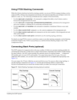
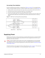
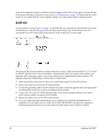
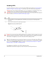
Connect the supplied AC power cord first to either receptacle of the S25P (on the right as you face the rear of the chassis) and then to the power source (see Power Requirements on page 34). Ensure that the cord is secure. If you connect both AC power supplies, ideally you would connect them to separate circuits. S25P-DC As shown below (see also Figure 4 on page 15), the S25P-DC (cat. name S25-01-GE-24P-DC) has two DC terminal blocks on the left side (as you face the front of the switch). The terminal block on the left corresponds to the DC1 status LED on the front left of the switch; DC2 is on the right. You must provide your own cables to connect to the power source. Cables must be sized for 11.5 A service at -48VDC input (per NEC in the United States. Internationally, follow local safety codes.) Before you make the cable connections, apply a coat of antioxidant paste to unplated metal contact surfaces. File unplated connectors, braided straps, and bus bars to a shiny finish. 1 Make sure that the remote power source (the circuit breaker panel) is in the OFF position. 2 Remove the safety cover from the DC terminal block. 3 Connect the grounding cable to the FG terminal first, then connect the opposite end to the appropriate grounding point at your site to ensure an adequate chassis ground. 4 Connect the -48 V and -48 V RTN (Return) cables to the switch terminals and then to the remote power sources, ideally on separate circuit breakers. 5 Replace the safety covers on the DC terminal blocks. 6 If you are connecting both terminal blocks, do not supply power until both terminal blocks are connected. You can supply power to either one or both. The S25P-DC uses the power supplies in load-sharing mode and does not set a precedence for either power source. Failover is hitless. 28 Installing the S25P
-
 1
1 -
2
-
3
-
4
-
5
-
6
-
7
-
8
-
9
-
10
-
11
-
12
-
13
-
14
-
15
-
16
-
17
-
18
-
19
-
20
-
21
-
22
-
 23
23 -
 24
24 -
 25
25 -
 26
26 -
 27
27 -
 28
28 -
 29
29 -
 30
30 -
 31
31 -
 32
32 -
 33
33 -
34
-
35
-
36
-
37
-
38
-
39
-
40
-
41
-
42
-
43
-
44
-
45
-
46
-
47
-
48
 |
 |
