Dell PowerEdge M1000e Dell PowerEdge M1000e Configuration Guide - Page 40
Tiering the Avocent iKVM Switch From a Digital KVM Switch - power requirements
 |
View all Dell PowerEdge M1000e manuals
Add to My Manuals
Save this manual to your list of manuals |
Page 40 highlights
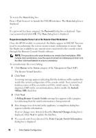
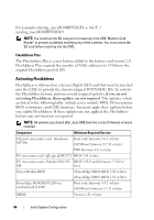
4 Click OK to exit OSCAR. 5 Press to verify that the settings have taken effect. The slot number of the blade to which the iKVM switch is now attached should be expanded to display each of the slot locations of the blades in the system. For instance, if the iKVM switch is attached to slot 1, it would now be displayed as 01-01 to 01-16. To connect the Avocent iKVM switch to a supported analog switch: 1 If the switch does not require a SIP to connect to the iKVM (see Table 2-1), connect a Cat5 (or newer) cable to the RJ-45 ACI port on the iKVM module. See Figure 1-16. Connect the other end of this cable to the ARI port on the external switch. If the analog switch requires a USB SIP (see Table 2-1), connect an Avocent USB SIP to the iKVM, then connect a Cat5 (or newer) cable to the SIP. Connect the other end of this cable to the ARI port on the external switch. 2 Connect both the analog switch and the system to an appropriate power source. 3 Turn on the system. 4 Turn on the external analog switch. NOTE: If the external analog switch is powered up before the system, it may result in only one blade being displayed in the analog switch OSCAR, instead of 16. If this behavior occurs, shut down and restart the switch so the entire complement of blades is recognized. NOTE: In addition to the steps outlined above, some external analog switches may require you to perform additional steps to ensure that the iKVM switch blades appear in the external analog switch OSCAR. See the external analog switch documentation for additional information. Tiering the Avocent iKVM Switch From a Digital KVM Switch The iKVM module may also be tiered from a digital KVM switch such as the Dell 2161DS-2 or 4161DS, or a supported Avocent digital KVM switch. Many switches may be tiered without the need for a SIP (see Table 2-2). 40 Initial System Configuration
-
 1
1 -
2
-
3
-
4
-
5
-
6
-
7
-
8
-
9
-
10
-
11
-
12
-
13
-
14
-
15
-
16
-
17
-
18
-
19
-
20
-
21
-
22
-
23
-
24
-
25
-
26
-
27
-
28
-
29
-
30
-
31
-
32
-
33
-
34
-
 35
35 -
 36
36 -
 37
37 -
 38
38 -
 39
39 -
 40
40 -
 41
41 -
 42
42 -
 43
43 -
 44
44 -
 45
45 -
46
-
47
-
48
-
49
-
50
-
51
-
52
-
53
-
54
-
55
-
56
-
57
-
58
-
59
-
60
-
61
-
62
-
63
-
64
-
65
-
66
-
67
-
68
-
69
-
70
-
71
-
72
-
73
-
74
-
75
-
76
-
77
-
78
-
79
-
80
-
81
-
82
-
83
-
84
-
85
-
86
 |
 |