Dell PowerEdge M1000e Dell PowerEdge M1000e Configuration Guide - Page 84
Ethernet Pass-Through Module, RJ45 Ethernet connector 16
 |
View all Dell PowerEdge M1000e manuals
Add to My Manuals
Save this manual to your list of manuals |
Page 84 highlights
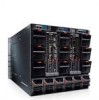
Figure 3-20. Ethernet Pass-Through Module 1 2 5 3 4 1 link indicator (16) 3 power indicator 5 activity indicator (16) 2 RJ45 Ethernet connector (16) 4 status/identification indicator NOTE: Connectors on the Ethernet pass-through module correspond directly to the blade number. For example, blade 5 is connected to port 5 on the Ethernet passthrough module. Integrated network adapter 1 maps to I/O slot A1. Integrated network adapter 2 maps to I/O slot A2. 84 Configuring the I/O Modules
-
 1
1 -
2
-
3
-
4
-
5
-
6
-
7
-
8
-
9
-
10
-
11
-
12
-
13
-
14
-
15
-
16
-
17
-
18
-
19
-
20
-
21
-
22
-
23
-
24
-
25
-
26
-
27
-
28
-
29
-
30
-
31
-
32
-
33
-
34
-
35
-
36
-
37
-
38
-
39
-
40
-
41
-
42
-
43
-
44
-
45
-
46
-
47
-
48
-
49
-
50
-
51
-
52
-
53
-
54
-
55
-
56
-
57
-
58
-
59
-
60
-
61
-
62
-
63
-
64
-
65
-
66
-
67
-
68
-
69
-
70
-
71
-
72
-
73
-
74
-
75
-
76
-
77
-
78
-
 79
79 -
 80
80 -
 81
81 -
 82
82 -
 83
83 -
 84
84 -
 85
85 -
 86
86
 |
 |

84
Configuring the I/O Modules
Figure 3-20.
Ethernet Pass-Through Module
NOTE:
Connectors on the Ethernet pass-through module correspond directly to the
blade number. For example, blade 5 is connected to port 5 on the Ethernet pass-
through module. Integrated network adapter 1 maps to I/O slot A1. Integrated
network adapter 2 maps to I/O slot A2.
1
link indicator (16)
2
RJ45 Ethernet connector (16)
3
power indicator
4
status/identification indicator
5
activity indicator (16)
1
5
2
3
4