Dell PowerEdge M1000e Dell PowerEdge M1000e Configuration Guide - Page 47
Configuring the I/O Modules, Overview
 |
View all Dell PowerEdge M1000e manuals
Add to My Manuals
Save this manual to your list of manuals |
Page 47 highlights
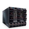
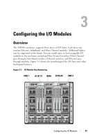
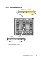
3 Configuring the I/O Modules Overview The M1000e enclosure supports three layers of I/O fabric. Each layer may contain Ethernet, Infiniband, and Fibre Channel modules. Additional fabrics may be supported in the future. You can install up to six hot-swappable I/O modules in the enclosure, including Fibre Channel switches, Fibre-Channel pass-throughs, Infiniband switches, Ethernet switches, and Ethernet passthrough modules. Figure 3-1 shows the numbering of the I/O bays and other back-panel features. Figure 3-1. I/O Module Bay Numbering CMC 1 A1 B1 C1 iKVM C2 B2 A2 CMC 2 1 2 3 4 5 6 7 8 9 12 3 4 5 6 Configuring the I/O Modules 47
-
 1
1 -
2
-
3
-
4
-
5
-
6
-
7
-
8
-
9
-
10
-
11
-
12
-
13
-
14
-
15
-
16
-
17
-
18
-
19
-
20
-
21
-
22
-
23
-
24
-
25
-
26
-
27
-
28
-
29
-
30
-
31
-
32
-
33
-
34
-
35
-
36
-
37
-
38
-
39
-
40
-
41
-
 42
42 -
 43
43 -
 44
44 -
 45
45 -
 46
46 -
 47
47 -
 48
48 -
 49
49 -
 50
50 -
 51
51 -
 52
52 -
53
-
54
-
55
-
56
-
57
-
58
-
59
-
60
-
61
-
62
-
63
-
64
-
65
-
66
-
67
-
68
-
69
-
70
-
71
-
72
-
73
-
74
-
75
-
76
-
77
-
78
-
79
-
80
-
81
-
82
-
83
-
84
-
85
-
86
 |
 |

Configuring the I/O Modules
47
3
Configuring the I/O Modules
Overview
The M1000e enclosure
supports three layers of I/O fabric. Each layer may
contain Ethernet, Infiniband, and Fibre Channel modules. Additional fabrics
may be supported in the future. You can install up to six hot-swappable I/O
modules in the enclosure, including Fibre Channel switches, Fibre-Channel
pass-throughs, Infiniband switches, Ethernet switches, and Ethernet pass-
through modules
. Figure 3-1 shows the numbering of the I/O bays and other
back-panel features.
Figure 3-1.
I/O Module Bay Numbering
1
2
3
4
5
6
7
8
9
1
2
3
4
5
6
A1 B1 C1
C2 B2 A2
CMC 1
CMC 2
iKVM