Dell XPS One 24 Service Manual - Page 34
Replace the five screws that secure the top end of the processor heat sink
 |
View all Dell XPS One 24 manuals
Add to My Manuals
Save this manual to your list of manuals |
Page 34 highlights
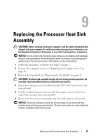
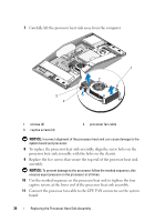
7 Carefully lift the processor heat sink away from the computer. 1 3 2 1 screws (4) 3 captive screws (4) 2 processor fan cable NOTICE: Incorrect alignment of the processor heat sink can cause damage to the system board and processor. 8 To replace the processor heat sink assembly, align the screw holes on the processor heat sink assembly with the holes on the chassis. 9 Replace the five screws that secure the top end of the processor heat sink assembly. NOTICE: To prevent damage to the processor follow the marked sequence, this ensures equal pressure on the processor at all times. 10 Use the marked sequence on the processor heat sink to tighten the four captive screws at the lower end of the processor heat sink assembly. 11 Connect the processor fan cable to the CPU FAN connector on the system board. 34 Replacing the Processor Heat Sink Assembly
-
 1
1 -
2
-
3
-
4
-
5
-
6
-
7
-
8
-
9
-
10
-
11
-
12
-
13
-
14
-
15
-
16
-
17
-
18
-
19
-
20
-
21
-
22
-
23
-
24
-
25
-
26
-
27
-
28
-
 29
29 -
 30
30 -
 31
31 -
 32
32 -
 33
33 -
 34
34 -
 35
35 -
 36
36 -
 37
37 -
 38
38 -
 39
39 -
40
-
41
-
42
-
43
-
44
-
45
-
46
-
47
-
48
-
49
-
50
 |
 |
