Dell XPS One 24 Service Manual - Page 39
Orient the front and rear alignment notches on the processor with
 |
View all Dell XPS One 24 manuals
Add to My Manuals
Save this manual to your list of manuals |
Page 39 highlights
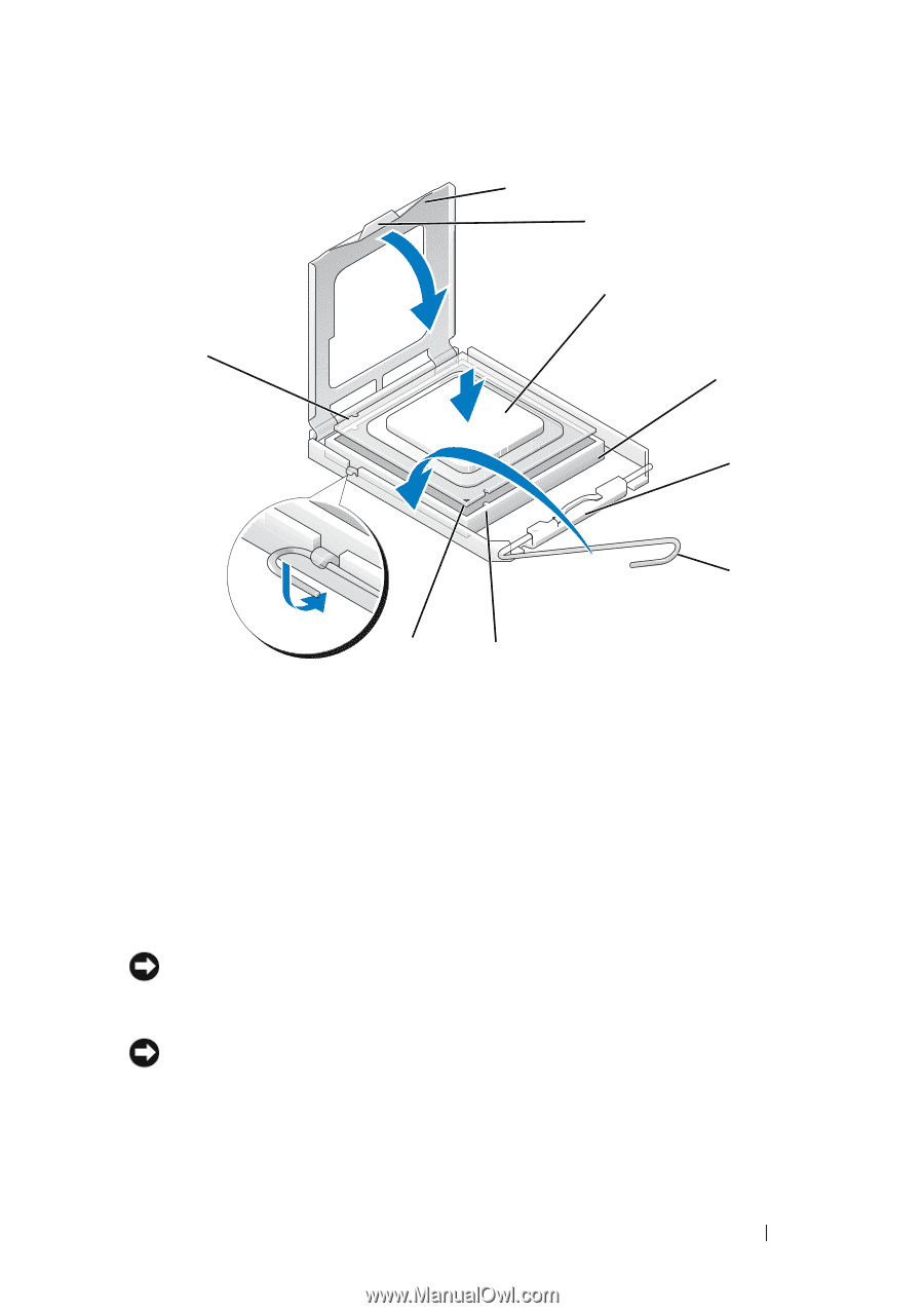
1 2 3 9 4 5 6 8 7 1 processor cover 3 processor 5 center cover latch 7 front alignment notch 9 rear alignment notch 2 tab 4 processor socket 6 release lever 8 processor pin-1 indicator 9 If the release lever on the socket is not fully extended, move it to that position. NOTICE: Socket pins are delicate. To avoid damage, ensure that the processor is aligned properly with the socket, and do not use excessive force when you install the processor. Be careful not to touch or bend the pins on the system board. NOTICE: You must position the processor correctly in the socket to avoid permanent damage to the processor. 10 Orient the front and rear alignment notches on the processor with the front and rear alignment notches on the socket. 11 Align the pin-1 corners of the processor and socket. Replacing the Processor 39
-
 1
1 -
2
-
3
-
4
-
5
-
6
-
7
-
8
-
9
-
10
-
11
-
12
-
13
-
14
-
15
-
16
-
17
-
18
-
19
-
20
-
21
-
22
-
23
-
24
-
25
-
26
-
27
-
28
-
29
-
30
-
31
-
32
-
33
-
 34
34 -
 35
35 -
 36
36 -
 37
37 -
 38
38 -
 39
39 -
 40
40 -
 41
41 -
 42
42 -
 43
43 -
 44
44 -
45
-
46
-
47
-
48
-
49
-
50
 |
 |