Denon AVR 1707 Owners Manual - English - Page 16
Connecting Other Sources - subwoofer
 |
UPC - 081757507127
View all Denon AVR 1707 manuals
Add to My Manuals
Save this manual to your list of manuals |
Page 16 highlights
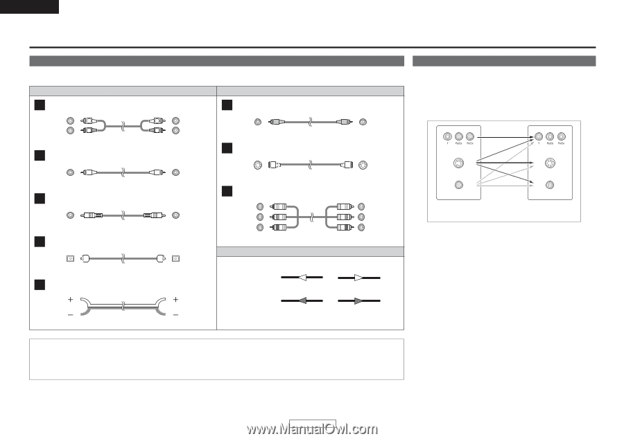
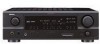
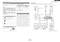
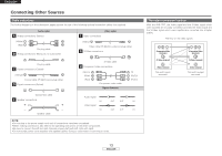
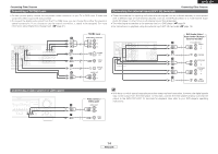
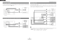
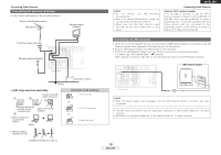
ENGLISH Connecting Other Sources Cable indications The hookup diagrams on the subsequent pages assume the use of the following optional connection cables (not supplied). Audio cable A Analog connections (Stereo) (White) (Red) L L R R Pin-plug cable B Analog connections (Monaural, for subwoofer) F Video connections Video cable (Yellow) Video cable (75 Ω/ohms video pin-plug cable) G S-Video connections Pin-plug cable C Digital connections (Coaxial) (Orange) Coaxial cable (75 Ω/ohms pin-plug cable) D Digital connections (Optical) S-Video cable H Component video connections (Green) (Blue) (Red) Component video cable Signal direction Optical fiber cable E Speaker connections Speaker cable Audio signal IN Video signal IN OUT OUT OUT OUT NOTE: • Do not plug in the power supply cord until all connections have been completed. • When making connections, also refer to the operating instructions of the other components. • Be sure to connect the left and right channels properly (left with left, right with right). • Do not bundle power cords together with speaker cables. Doing so could result in humming or noise. (Y) (PB/CB) (PR/CR) IN IN The video conversion function With the AVR-1707, the Video signal and the S-Video signal which were inputted are mutually converted. And also the Video signal and the S-Video signal which were inputted are converted into a higher quality. The flow of the video signals. (Component Video terminals) (S-Video terminal) (Video terminal) This unit's input terminals (Component Video terminals) (S-Video terminal) (Video terminal) This unit's output terminals 13 ENGLISH
-
 1
1 -
2
-
3
-
4
-
5
-
6
-
7
-
8
-
9
-
10
-
 11
11 -
 12
12 -
 13
13 -
 14
14 -
 15
15 -
 16
16 -
 17
17 -
 18
18 -
 19
19 -
 20
20 -
 21
21 -
22
-
23
-
24
-
25
-
26
-
27
-
28
-
29
-
30
-
31
-
32
-
33
-
34
-
35
-
36
-
37
-
38
-
39
-
40
-
41
-
42
-
43
-
44
-
45
-
46
-
47
-
48
-
49
-
50
-
51
-
52
-
53
-
54
-
55
-
56
-
57
-
58
-
59
-
60
-
61
-
62
-
63
-
64
 |
 |