Epson 2200 Service Manual
Epson 2200 - Stylus Photo Color Inkjet Printer Manual
 |
UPC - 010343841840
View all Epson 2200 manuals
Add to My Manuals
Save this manual to your list of manuals |
Epson 2200 manual content summary:
- Epson 2200 | Service Manual - Page 1
SERVICE MANUAL Color Inkjet Printer EPSON Stylus PHOTO 2100/2200 ® SEIJ01-016 - Epson 2200 | Service Manual - Page 2
Notice ! All rights reserved. No part of this manual may be reproduced, stored in a retrieval system, or transmitted in any form or by any means electronic, mechanical, photocopying, or otherwise, without the prior written permission of SEIKO EPSON CORPORATION. ! All effort have been made to ensure - Epson 2200 | Service Manual - Page 3
INSTRUCTED TO DO SO. WHEN THE POWER SUPPLY CABLE MUST BE CONNECTED, USE EXTREME CAUTION IN WORKING ON POWER SUPPLY AND OTHER ELECTRONIC COMPONENTS. 4. WHEN DISASSEMBLING OR ASSEMBLING A PRODUCT, MAKE SURE TO WEAR GLOVES TO AVOID INJURIER FROM METAL PARTS WITH SHARP EDGES. WARNING 1. REPAIRS ON EPSON - Epson 2200 | Service Manual - Page 4
and repair procedures of the printer. The instructions and procedures included herein are intended for the experienced repair technicians, and attention should be given to the precautions on the preceding page. Manual Configuration Symbols Used in this Manual This manual consists of six chapters - Epson 2200 | Service Manual - Page 5
Revision Status Revision A B Issued Date May 24, 2002 August 22, 2002 Description First Release Page 212 Modify the wrong description on the A3+ size Photo Quality Ink Jet Paper Check pattern (first solid pattern) Page 213 The description for A4 size Plain Paper check point was added. - Epson 2200 | Service Manual - Page 6
PRINCIPLES 2.1 Overview 40 2.2 Printer Mechanism 40 2.2.1 Carriage Mechanism 41 2.2.2 Print Mode 44 2.2.3 Paper Feeding Mechanism 48 2.2.4 Paper Loading Mechanism 54 2.2.5 Ink System Mechanism 58 2.2.6 Ink Sequence 60 2.2.7 Paper Cutter Mechanism 63 2.2.8 Power-On Sequence 65 2.3 Electrical - Epson 2200 | Service Manual - Page 7
Replacement 215 6.1.2 Cleaning 215 6.1.3 Service Maintenance 216 6.1.4 Lubrication 217 Chapter 7 APPENDIX 7.1 Connector Summary 227 7.1.1 Connectors and Pin Layouts 227 7.1.2 EEPROM Address Map 231 7.2 Exploded Diagram 236 7.3 Parts List for EPSON Stylus Photo 2100 248 7.4 Circuit Diagram 253 - Epson 2200 | Service Manual - Page 8
PRODUCTION DESCRIPTION CHAPTER 1 - Epson 2200 | Service Manual - Page 9
EPSON Stylus PHOTO 2100/2200 1.1 Overview The Stylus PHOTO 2100/2200 is a photo printer designed for a wide range of users from individual users to commercial users. As a model to replace the Stylus PHOTO 2000P, this consumer high-end model is capable of pigment-independent CSIC, CD-R printing, and - Epson 2200 | Service Manual - Page 10
EPSON Stylus PHOTO 2100/2200 Revision B 1.2 Basic Specifications 1.2.1 Specification Outline Comparison The following table gives the comparison of specifications between this product and similar conventional models. Head Item Location Number of colors Resolution (H × V) Cut sheet size Roll - Epson 2200 | Service Manual - Page 11
EPSON Stylus PHOTO 2100/2200 Ink cartridges Table 1-1. Specification Outline Comparison Item Stylus PHOTO 950 Stylus PHOTO 2100/2200 Ink type Dye Newly developed pigment Ink cartridge type Color-separated CSIC Color-separated CSIC I/C (T code : Overseas) • T0331 (Bk) • T0332 (C) • T0333 - Epson 2200 | Service Manual - Page 12
number of print digits (10CPI) Number of motors *1 : Optional cutter CR motor armature resistance ASF/PUMP motor winding resistance PF motor armature resistance (ASF) Platen gap Reliability (except head) Operation noise (ISO 7779) Stylus PHOTO 950 86.97 digits Stylus PHOTO 2100/2200 127 digits - Epson 2200 | Service Manual - Page 13
EPSON Stylus PHOTO 2100/2200 Revision B Sensors Main board Power board Panel board Item CR encoder PF encoder PE detector PE detector (rear) PG detector Paper leading edge/ paper width detector (PW sensor) I/C detector ASF - Epson 2200 | Service Manual - Page 14
measurement PF Adjustment (Band feed adjustment) Top margin adjustment PW sensor mounting position adjustment PF backlash adjustment Maintenance Lubricating oil/ grease Waste ink pad Table 1-1. Specification Outline Comparison Stylus PHOTO 950 Stylus PHOTO 2100/2200 EEPROM write EEPROM - Epson 2200 | Service Manual - Page 15
EPSON Stylus PHOTO 2100/2200 1.2.2 Paper Specification 1.2.2.1 Cut Sheet (Anti-EPSON special media) Table 1-2. be used. " No curled paper more than 5mm be used. Revision B 1.2.2.2 Envelope (Anti-EPSON special media) Table 1-3. Envelope Paper size #10 *a Paper Paper width mm length mm (inch - Epson 2200 | Service Manual - Page 16
EPSON Stylus PHOTO 2100/2200 Revision B 1.2.2.3 EPSON Special media Quality: EPSON specifically designed media for ink jet printers Table 1-4. EPSON Special media EPSON Special media Paper size Paper width mm (inch) Paper length mm (inch) Quality mm Weight g/m2 (Ib) ASF Support setting - Epson 2200 | Service Manual - Page 17
EPSON Stylus PHOTO 2100/2200 Revision B Table 1-4. EPSON Special media EPSON Special media Paper size Paper width mm (inch) Paper length mm (inch) Quality mm Weight g/m2 (Ib) Super A3/B 329 483 A3 297 420 Matte Paper- A4 Heavyweight 210 297 0.23 167(44) 89 7m ASF Support setting - Epson 2200 | Service Manual - Page 18
EPSON Stylus PHOTO 2100/2200 Table 1-5. Printing Area (mm) of Stylus PHOTO 2100/2200 Paper size PW (paper width) PL (paper length) LM (Left command, the bottom margin can be reduced to the minimum of 3mm. However, printing quality may decline in the range 3mm to 14mm from the paper bottom. When - Epson 2200 | Service Manual - Page 19
EPSON Stylus PHOTO 2100/2200 " Printable area (Margin-less printing) The range made of the printable areas A and B and the top, bottom, left and right off-range printing areas C shown in Figure 1-4.The image quality levels of the printing areas A, B are defined in the quality standard. The printing - Epson 2200 | Service Manual - Page 20
EPSON Stylus PHOTO 2100/2200 2. At the setting of top margin to 0mm Top off-range printing prints the area a, and nozzle-restricted printing prints the area c. After the #1 nozzle has passed through the area c, nozzle restriction is canceled. 2) Bottom head movable area 1. At the setting of bottom - Epson 2200 | Service Manual - Page 21
EPSON Stylus PHOTO 2100/2200 3. At the setting of bottom margin to 0mm Since printing is restricted in the bottom off-range area (e) after the distance f from the paper bottom, only a total of 14 nozzles, #66 to #79, are used per nozzle line to perform printing. Revision B ! Printing area (Roll - Epson 2200 | Service Manual - Page 22
EPSON Stylus PHOTO 2100/2200 ! Printing area (CD-R) " Printing area Figure 1-11 shows a CD-R printing area. The printing area is in the inside of reversed more than 74mm from the head #1 nozzles. Revision B Figure 1-11. Printing Area Diagram (CD-R) PRODUCTION DESCRIPTION Basic Specifications 22 - Epson 2200 | Service Manual - Page 23
EPSON Stylus PHOTO 2100/2200 1.2.4 Ink Type-based Medium Compatibility Specifications On this product, the compatible media change depending on the black ink combination. PIM compatibility also changes depending on the medium. The following describes the compatible media, used LUT, and PIM - Epson 2200 | Service Manual - Page 24
EPSON Stylus PHOTO 2100/2200 ! Matte-black + Light-black: Matte-black is optional. Good-looking ink combination for plain paper/matte-Light-black media Paper Type Plain Paper Table 1-8. Matte-black + Light-black Support Used LUT Driver UI Description US Other # Plain Paper Plain Paper - Epson 2200 | Service Manual - Page 25
EPSON Stylus PHOTO 2100/2200 1.2.5 Release Lever On this printer, set the Release lever as indicated in the following table depending on the used paper type. Table 1-9. Release lever Setting Paper Release lever Position Gap - Epson 2200 | Service Manual - Page 26
EPSON Stylus PHOTO 2100/2200 1.3 Functions 1.3.1 Control Panel The appearance of the control panel is shown below. Ink LEDs 1 to 7 Roll paper switch Ink switch Paper switch Power LED Paper LED Power switch Figure 1-13. Control Panel Appearance 1.3.2 Switches ! Power switch ! Paper switch ! Ink - Epson 2200 | Service Manual - Page 27
EPSON Stylus PHOTO 2100/2200 FUNCTIONS AT POWER-ON Table 1-11. Power-on Functions Switch Function Paper switch Status printing *a Ink switch Roll paper switch Paper switch + Roll paper switch Roller cleaning mode *b Code Page/parallel interface 1284.4 operation mode selection *c Special - Epson 2200 | Service Manual - Page 28
EPSON Stylus PHOTO 2100/2200 1.3.5 Default Setting Selection Function CODE PAGE SELECTION FUNCTION By operating the panel at power-on, you can select the default character code table. Operating procedure Hold down the Roll paper switch and switch power on or reset the panel. When the blink of - Epson 2200 | Service Manual - Page 29
EPSON Stylus PHOTO 2100/2200 1.3.6 Special Setting Mode Function EEPROM AND TIMER IC RESET By operating the panel at power-on, you can reset the EEPROM and Timer IC. Operating procedure Hold down the Roll paper switch and Paper switch, and switch power on. When the blink 2 of the Power and - Epson 2200 | Service Manual - Page 30
EPSON Stylus PHOTO 2100/2200 1.3.7 Status Printing PRINTING METHOD ! Printing using remote command Use the NC command of the remote commands. ! Status printing Hold down the Paper switch and switch power on. ! Printing using D4 control command On the D4 command channel, send the "nc" command. - Epson 2200 | Service Manual - Page 31
EPSON Stylus PHOTO 2100/2200 1.3.8 Panel Operation for Roll Paper Printing PANEL OPERATION IN ROLL PAPER MODE (WITHOUT CUTTER, TEAR-OFF LINE PRINTING EEPROM. When power is switched on again, the printer does not eject paper. The operation that follows can be performed. *d : If power is switched off - Epson 2200 | Service Manual - Page 32
EPSON Stylus PHOTO 2100/2200 At this time, there are no print margins between the jobs. If there is a next print jog, the printer prints and Steps 2. and 3. are When power is switched on again, the printer does not eject paper. The operation in Step 2. and later can be performed. *b : If power is - Epson 2200 | Service Manual - Page 33
EPSON Stylus PHOTO 2100/2200 1.3.9 Panel Operation for CD-R Printing The following indicates the basic panel operating procedure for printing on CD-R. Operating procedure 1. Move the Release lever to the farthest position. 2. Along the paper feed guide, put the CD-R tray folder into the printer - Epson 2200 | Service Manual - Page 34
EPSON Stylus PHOTO 2100/2200 1.3.11 Panel Operation in Roller Cleaning Mode If the ink concentration is increased within the printer driver detail setting, the ink printed on the medium may be transferred to the rollers. In this case, the ink may be transferred from the rollers to the print medium, - Epson 2200 | Service Manual - Page 35
EPSON Stylus PHOTO 2100/2200 1.3.12 Indicator Display in Normal Mode Table 1-13. Printer Condition and LED Status Printer status Power on condition Data processing Ink sequence Ink cartridge change mode Ink level low Paper out Ink end Ink color error Ink combination error No ink cartridge or Ink - Epson 2200 | Service Manual - Page 36
EPSON Stylus PHOTO 2100/2200 1.3.13 Error Status If any of the following states is detected, this printer is put in an error status and turns the interface signal -ERROR "Low" and BUSY "High" to inhibit data input. At this time, the printer is automatically disabled from printing. However, when - Epson 2200 | Service Manual - Page 37
EPSON Stylus PHOTO 2100/2200 1.4 Casing Specifications EXTERNAL DIMENSIONS When tucked When used : 631 (width) × 320 (depth) Dimension Diagram Revision B 1.5 Accessories STANDARD ACCESSORIES ! Instruction manual ! Ink cartridge ! CD-ROM (Printer driver utility) ! Roll paper holder ! Sheet ! - Epson 2200 | Service Manual - Page 38
EPSON Stylus PHOTO 2100/2200 1.6 Environment Specification Items Main unit Table 1-14. Environment Specification Items Class Details Resource usage reduction Product Capacity Product weight Total amount of power consumption Energy saving Turn-off power consumption Compliance with the - Epson 2200 | Service Manual - Page 39
OPERATING PRINCIPLES CHAPTER 2 - Epson 2200 | Service Manual - Page 40
compatibility with CD-R label direct printing, the CD-R tray adaptor and exclusive sensor are loaded. (Only for Stylus PHOTO 2100) • To feed board paper and roll paper, the exclusive paper feed guide is fitted. • For compatibility with the CD-R tray and correction of ink transfer to the roller, the - Epson 2200 | Service Manual - Page 41
EPSON Stylus PHOTO 2100/2200 Revision B 2.2.1 Carriage Mechanism The Carriage mechanism consists of the Carriage motor (CR motor), Carriage guide shafts A (main shaft), B (sub shaft), Platen gap adjustment mechanism, Carriage lock mechanism, and others. 2.2.1.1 Carriage Motor (CR Motor) Like the - Epson 2200 | Service Manual - Page 42
EPSON Stylus PHOTO 2100/2200 Revision B 2.2.1.2 Carriage Home Position Detection To detect the Carriage home position, the drive current of the CR motor and the speed/ position signal of the CR linear encoder are used as in the conventional Stylus PHOTO when power is switched , the printer judges it - Epson 2200 | Service Manual - Page 43
EPSON Stylus PHOTO 2100/2200 2.2.1.3 Sequence Used for PW Detection The PW detector on the Carriage unit bottom performs the following sequence. ! Off-paper printing prevention control Before start of printing (immediately after the end of paper locating) or during printing at every power-on, and - Epson 2200 | Service Manual - Page 44
EPSON Stylus PHOTO 2100/2200 Revision B However, the white level value is not used in the PW sensor-related firmware processing. The white level value is used to check the sensor deterioration condition during servicing or like. If the measurement value of the white level is close to that of the - Epson 2200 | Service Manual - Page 45
EPSON Stylus PHOTO 2100/2200 Revision B 2.2.2.2 Ink Combinations and Corresponding Printing Resolutions and Printing Methods The printing resolution and printing method are determined by setting the "Print medium" and "Printing quality" (can be set using the slide bar) on the printer driver - Epson 2200 | Service Manual - Page 46
EPSON Stylus PHOTO 2100/2200 Revision B Table 2-6. Manual Setting (Color & Black) Photo-black + Light-black Print Medium Print Mode Resolution Bi-directional Printing Microwave Dot Size Draft /Draft *1 360×360 ON OFF Variable 1 Plain Paper Normal-360 /Fine 360×360 ON/OFF ON (95) - Epson 2200 | Service Manual - Page 47
EPSON Stylus PHOTO 2100/2200 Table 2-8. Manual Setting (Color & Black) Matte-black + Light-black Print Medium Print Mode Resolution Bi-directional Printing Microwave Dot Size Draft /Draft*2 360×360 ON OFF Variable 1 Plain Paper Normal-360 /Fine 360×360 ON/OFF ON (95) Variable 1 - Epson 2200 | Service Manual - Page 48
EPSON Stylus PHOTO 2100/2200 Revision B 2.2.2.4 Pseudo Four-color Mode This print mode can be selected in the detail setting mode when the plain paper is selected, and means the draft mode. In this mode, the printer operates as a pseudo four-color printer, with Lines A and B used for one color of - Epson 2200 | Service Manual - Page 49
EPSON Stylus PHOTO 2100/2200 the Carriage unit moves leftward from the right end of the Carriage guide shaft by the specified number of steps, the DE lock lever fixes 14, 28 → Spur gear 32 (ASF side) The following shows the part names and operation outline of the DE mechanism. Combination gear 14, 28 - Epson 2200 | Service Manual - Page 50
EPSON Stylus PHOTO 2100/2200 including that of the double-feed prevention mechanism. 1. At power-on, the ASF/Pump motor rotates in the CCW direction Figure 2-7, "Paper Feeding Operation". 4. Then when you give a print command and press the Paper switch on the panel, the ASF/ Printer Mechanism 50 - Epson 2200 | Service Manual - Page 51
EPSON Stylus PHOTO 2100/2200 Revision B 2.2.3.4 Manual Paper Feeding Mechanism (Board Paper) To enable direct printing onto thick paper and CD-R label, this product has the mechanism to feed paper from the printer front and rear manually. Move the Release lever to the farthest position, insert - Epson 2200 | Service Manual - Page 52
EPSON Stylus PHOTO 2100/2200 ! When 01 is written and cutter is not fitted Pressing the Roll paper cut switch after end of printing prints a tear-off line and feeds the roll paper to the roll paper cut position. When you cut the roll paper with scissors or like and - Epson 2200 | Service Manual - Page 53
EPSON Stylus PHOTO 2100/2200 2.2.3.6 CD-R Printing Mechanism (Only for Stylus PHOTO 2100) ! CD-R tray home position detection Release lever setting position is other than the CD-R position. OPERATING PRINCIPLES Printer Mechanism Revision B Carriage unit PW sensor CD-R home position (White label - Epson 2200 | Service Manual - Page 54
EPSON Stylus PHOTO 2100/2200 Revision B 2.2.4 Paper Loading Mechanism The Paper loading mechanism is designed to transfer the paper fed from the ASF, Roll paper guide or Board paper guide or the CD-R fed from the CD-R tray according to the print The following shows the part names and outline of - Epson 2200 | Service Manual - Page 55
EPSON Stylus PHOTO 2100/2200 Revision B The paper fed from the ASF, Roll paper guide or Board paper guide is detected by the PE sensor installed on the right side of the Upper frame, and its leading edge is transferred to the center front of the Paper guide once. To eliminate the deflection of the - Epson 2200 | Service Manual - Page 56
EPSON Stylus PHOTO 2100/2200 2.2.4.3 Paper Mode Setting The paper mode that matches the print medium is selected according to the statuses of the PE sensor, CD-R sensor (Only for Stylus PHOTO 2100) and Release lever (sensor) to determine the paper loading sequence (paper locating control). The - Epson 2200 | Service Manual - Page 57
EPSON Stylus PHOTO 2100/2200 2.2.4.4 PG Detection ( Stylus PHOTO 2100) Release ON ON - Note: When the PG position is the + position (PG sensor: OFF, Release sensor: OFF, Setting mode: Board paper, Thick paper), the printing method is forcibly changed to Uni-D. OPERATING PRINCIPLES Printer - Epson 2200 | Service Manual - Page 58
EPSON Stylus PHOTO 2100/2200 Revision B 2.2.5 Ink System Mechanism The Ink system mechanism consists of the Pump unit (including the Carriage lock lever) and Capping mechanism. The Cap unit is in close contact with the CR unit and drains ink from the Ink cartridge to Head guide the part names - Epson 2200 | Service Manual - Page 59
EPSON Stylus PHOTO 2100/2200 Revision B The following diagram shows the pump operating principle. 1. When the Pump unit is rotated by the ASF/Pump motor in the CW direction, the turning roller presses the tube. Therefore, ink is fed from the Cap unit toward the Waste ink pad. 2. When the Pump unit - Epson 2200 | Service Manual - Page 60
EPSON Stylus PHOTO 2100/2200 2.2.6 Ink Sequence The following ink sequence is executed according to various timer, counter, flag and other information saved on the EEPROM. ! CSIC-related sequence The ink type 1 code stored in the CSIC memory chip is identical regardless of the Japanese domestic or - Epson 2200 | Service Manual - Page 61
EPSON Stylus PHOTO 2100/2200 Revision B ! Initial ink filling When the printer is powered on for the first time after the purchase of the product, the printer executes the initial ink filling operation to fill the ink cavities of the Head with ink. When the initial ink filling operation is - Epson 2200 | Service Manual - Page 62
EPSON Stylus PHOTO 2100/2200 ! Manual cleaning This product provides four different manual cleanings to remove ink coagulated by air bubbles, viscous material or foreign matter. Perform the following manual CL operations by operating the panel or using the utility included in the printer driver. - Epson 2200 | Service Manual - Page 63
EPSON Stylus PHOTO 2100/2200 ! Timer cleaning This printer consumes the ink of up to 1.27g/color depending on the combination of the cumulative printing timer, cumulative cleaning count and cleaning timer. ! Flushing This printer executes two different flushings for the following purposes. " - Epson 2200 | Service Manual - Page 64
EPSON Stylus PHOTO 2100/2200 Revision B 2.2.7.1 Cutter Initialization Sequence When the Cutter is fitted, the cutter initialization sequence is executed if the printer has confirmed that the Cutter has been fitted (the Power switch blinks about 5 seconds). The cutter initialization sequence is an - Epson 2200 | Service Manual - Page 65
EPSON Stylus PHOTO 2100/2200 2.2.8 Power-On Sequence The following explains the operation to be performed when there is paper or no paper and the Carriage is inside or outside the HP with the printer powered on. ! Without paper/Carriage inside HP (CR locked) 1. When power is switched on, the drive - Epson 2200 | Service Manual - Page 66
EPSON Stylus PHOTO 2100/2200 2.3 Electrical Circuitry Operating Principles The electrical circuitry of this product consists of the following circuits. ! Control circuit board C387 MAIN ! Power supply circuit board C387 PSB/PSE ! Control panel board C387 PNL The following shows how the three - Epson 2200 | Service Manual - Page 67
EPSON Stylus PHOTO 2100/2200 2.3.1 Power Supply Circuit Operating Principle The power supply circuit board of this product is the C387 PSB/PSE. The basic structure of the circuit uses the RCC switching regulator method and +42VDC and +5DVC are supplied to the printer mechanism and control boards. - Epson 2200 | Service Manual - Page 68
EPSON Stylus PHOTO 2100/2200 Revision B 2.3.2 C387MAIN Circuit Operating Principle The C387MAIN board consists of the logic circuits (CPU, ASIC, PROM, SDRAM, 1394 controller, USB2.0 controller), various motor control/drive circuits (CR motor, PF motor, ASF/Pump motor), head • Ink cartridge sensor - Epson 2200 | Service Manual - Page 69
TROUBLESHOOTING CHAPTER 3 - Epson 2200 | Service Manual - Page 70
EPSON Stylus PHOTO 2100/2200 Revision B 3.1 Overview This chapter describes unit-level troubleshooting. 3.2 Error Indications and Fault Occurrence Causes This section explains the LED indications, EPW3 messages and fault occurrence causes at occurrence of the following errors during - Epson 2200 | Service Manual - Page 71
EPSON Stylus PHOTO 2100/2200 Revision B Printer Condition Release Lever Error Indicators Power Paper - High speed Blink Table 3-1. Error Indications and Fault Occurrence Causes Ink 1-7 - EPSON Printer Window 3 Fault Occurrence Cause This error is detected in the following case. The - Epson 2200 | Service Manual - Page 72
EPSON Stylus PHOTO 2100/2200 Revision B Printer Condition Paper Jam Error Power - Indicators Paper Blink Table 3-1. Error Indications and Fault Occurrence Causes Ink 1-7 - EPSON Printer the printer judges that the Carriage made contact with the paper, which was fed from the Paper guide manual - Epson 2200 | Service Manual - Page 73
EPSON Stylus PHOTO 2100/2200 Revision B Printer Condition Double Feed Error Power - Indicators Paper On Table 3-1. Error Indications and Fault Occurrence Causes Ink 1-7 - EPSON Printer Window 3 Fault Occurrence Cause This error is detected if a paper feeding displacement occurred between the - Epson 2200 | Service Manual - Page 74
EPSON Stylus PHOTO 2100/2200 Revision B Printer Condition Ink Color Error Power - Table 3-1. Error Indications and Fault Occurrence Causes Indicators Paper - Ink 1-7 High speed Blink EPSON Printer Window 3 Fault Occurrence Cause This error is detected if Ink end/low occurs during printing - Epson 2200 | Service Manual - Page 75
EPSON Stylus PHOTO 2100/2200 Revision B Printer Condition Ink End Error Power - Indicators Paper - Table 3-1. Error Indications and Fault Occurrence Causes Ink 1-7 On EPSON Printer Window 3 Fault Occurrence Cause This error is detected in either of the following cases. 1. The ink consumption - Epson 2200 | Service Manual - Page 76
EPSON Stylus PHOTO 2100/2200 Revision B Printer Condition Cutter Jam Error Power - Indicators Paper Blink 2 Table 3-1. Error Indications and Fault Occurrence Causes Ink 1-7 - EPSON Printer : 0.5sec on + 0.5sec on repetition TROUBLESHOOTING Error Indications and Fault Occurrence Causes 76 - Epson 2200 | Service Manual - Page 77
EPSON Stylus PHOTO 2100/2200 Revision B Printer Condition Maintenance Request Table 3-1. Error Indications and Fault Occurrence Causes Indicators Power Paper Ink 1-7 Off Blink alternately 1 Blink alternately 2 EPSON Printer TROUBLESHOOTING Error Indications and Fault Occurrence Causes 77 - Epson 2200 | Service Manual - Page 78
EPSON Stylus PHOTO 2100/2200 Revision B 3.3 Troubleshooting After checking the printer LED and EPW3 Ink End Error Refer to Table 3-12 Phenomenon-Based Ink End Error Check Points on page 90. No Ink Cartridge/Ink Cartridge Error Refer to Table 3-13 Phenomenon-Based No Ink Cartridge/Ink Cartridge - Epson 2200 | Service Manual - Page 79
EPSON Stylus PHOTO 2100/2200 Revision B Table 3-3. "Phenomenon-Based Communication Error Check Points" Occurrence Timing Phenomenon Detail At power-on The printer does not operate at all. Faulty Part/ Part Name Panel FFC Check Point 1. Check that the Panel FFC is connected to the connector of - Epson 2200 | Service Manual - Page 80
EPSON Stylus PHOTO 2100/2200 Revision B Table 3-3. "Phenomenon-Based Communication Error Check Points" Occurrence Timing Phenomenon Detail At power-on The printer does not operate at all. Faulty Part/ Part Name Power supply board Check Point Remedy 3. Check that the Fuse (F1) on the Power - Epson 2200 | Service Manual - Page 81
EPSON Stylus PHOTO 2100/2200 Revision B Table 3-3. "Phenomenon-Based Communication Error Check Points" Occurrence Timing Phenomenon Detail At operation Operation at power-on is normal, but the error appears when the print jog is sent to the printer. Faulty Part/ Part Name IEEE1394 Check - Epson 2200 | Service Manual - Page 82
EPSON Stylus PHOTO 2100/2200 Revision B Occurrence Timing Phenomenon Detail At power-on At power-on, the Paper guide of the Printer mechanism is open and Release lever error is displayed. The Release lever is in the front position and the Paper guide is closed but Release lever error is - Epson 2200 | Service Manual - Page 83
EPSON Stylus PHOTO 2100/2200 Revision B Occurrence Timing Phenomenon Detail At operation When the Paper switch was pressed, the LD rollers attempt to feed paper but the paper is not fed. Table 3-5. Phenomenon-Based Paper Out Error Check Points Faulty Part/ Part Name ASF unit Check Point - Epson 2200 | Service Manual - Page 84
EPSON Stylus PHOTO 2100/2200 Revision B Occurrence Timing Phenomenon Detail At operation After start of printing operation, the LD rollers attempt to feed paper but the paper is not fed. Table 3-5. Phenomenon-Based Paper Out Error Check Points Faulty Part/ Part parts the above photo.) 4. Using - Epson 2200 | Service Manual - Page 85
EPSON Stylus PHOTO 2100/2200 Revision B Occurrence Timing Phenomenon Detail The Paper feed switch The CD-R tray is fed toward the was pressed at the ASF but is ejected immediately. setting of the CD-R tray. (Only for Stylus PHOTO approximate to each other. TROUBLESHOOTING Troubleshooting 85 - Epson 2200 | Service Manual - Page 86
EPSON Stylus PHOTO 2100/2200 Revision B Occurrence Timing Phenomenon Detail The Paper feed switch The CD-R tray is fed up to the was pressed at the Driven roller section toward the setting of the CD-R ASF, but is kept fed for some tray. time toward the ASF and is then (Only for Stylus - Epson 2200 | Service Manual - Page 87
EPSON Stylus PHOTO 2100/2200 Revision B Occurrence Timing Phenomenon Detail At power-on At power-on, the PF roller turns (ASF, board paper continuously for several seconds. feed mode only) Table 3-6. Phenomenon-Based Paper Jam Error Check Points Faulty Part/ Part Name PE sensor Check Point - Epson 2200 | Service Manual - Page 88
EPSON Stylus PHOTO 2100/2200 Revision B Occurrence Timing Phenomenon Detail At operation Paper is not ejected completely and causes a jam near the Paper eject frame. Table 3-6. Phenomenon-Based Paper Jam Error Check Points Faulty Part/ Part Name Check Point ASF unit 1. Check that the paper - Epson 2200 | Service Manual - Page 89
EPSON Stylus PHOTO 2100/2200 Revision B Table 3-7. "Phenomenon-Based Paper Gap Error Check Points Occurrence Timing Phenomenon Detail Paper was fed from Thick paper is fed but not printed. the Board paper guide and the Carriage executed paper locating control or paper width detection. Faulty - Epson 2200 | Service Manual - Page 90
EPSON Stylus PHOTO 2100/2200 Revision B Occurrence Timing Phenomenon Detail The Ink cartridge was When you changed the Ink changed during cartridge and pressed the Ink printing due to Ink switch, the error appears on the end/low. LED and EPW3. Table 3-10. Phenomenon-Based Ink Color Error - Epson 2200 | Service Manual - Page 91
EPSON Stylus PHOTO 2100/2200 Revision B Table 3-13. Phenomenon-Based No Ink Cartridge/Ink Cartridge Error Check Points Occurrence Timing Phenomenon Detail At power-on After the Carriage has detected the home position, the error appears on the LED and EPW3. Faulty Part/ Part Name Ink cartridge - Epson 2200 | Service Manual - Page 92
EPSON Stylus PHOTO 2100/2200 Revision B Table 3-13. Phenomenon-Based No Ink Cartridge/Ink Cartridge Error Check Points Occurrence Timing Phenomenon Detail At power-on After the Carriage has detected the home position, the error appears on the LED and EPW3. Faulty Part/ Part Name Carriage unit - Epson 2200 | Service Manual - Page 93
EPSON Stylus PHOTO 2100/2200 Revision B Occurrence Timing Phenomenon Detail At roll paper feeding After the roll paper is fed, the by auto loading Paper LED indicates Blink 2. Table 3-14. Phenomenon-Based Cutter Jam Error Check Points Faulty Part/ Part Name Cutter motor Check Point Remedy - Epson 2200 | Service Manual - Page 94
EPSON Stylus PHOTO 2100/2200 Revision B Occurrence Timing Phenomenon Detail At Cutter unit fitting (At power-on) At power-on, the Carriage produces operating Cutter HP sensor (right) to CN4 on the Driver board securely. 3. Change the Cutter HP sensor (right) for a new one. Troubleshooting 94 - Epson 2200 | Service Manual - Page 95
EPSON Stylus PHOTO 2100/2200 Revision B Table 3-16. Phenomenon-Based Maintenance Request Check Points Occurrence Timing Phenomenon Detail Faulty Part/Part Name Check Point Remedy At power-on At power-on, the printer does not operate at all. Waste ink pads 1. Using the adjustment program, - Epson 2200 | Service Manual - Page 96
EPSON Stylus PHOTO 2100/2200 Revision B Table 3-17. Phenomenon-Based Fatal Error Check Points Occurrence Timing Phenomenon Detail Faulty Part/Part Name Check Point Remedy At power-on At power 1. Wipe the surfaces of the CR guide shafts A and B with a dry TROUBLESHOOTING Troubleshooting 96 - Epson 2200 | Service Manual - Page 97
EPSON Stylus PHOTO 2100/2200 Revision B Table 3-17. Phenomenon-Based Fatal Error Check Points Occurrence Timing Phenomenon Detail Faulty Part/Part Name Check Point Remedy At power-on The power-on for a new one. 3. Change the PF motor for a new one. TROUBLESHOOTING Troubleshooting 97 - Epson 2200 | Service Manual - Page 98
EPSON Stylus PHOTO 2100/2200 Revision B Table 3-17. Phenomenon-Based Fatal Error Check Points Occurrence Timing Phenomenon Detail Faulty Part/Part Name Check Point Remedy At power-on At power-on, . 2. Change the Extension spring 0.618 for a new one. TROUBLESHOOTING Troubleshooting 98 - Epson 2200 | Service Manual - Page 99
EPSON Stylus PHOTO 2100/2200 Revision B Table 3-17. Phenomenon-Based Fatal Error Check Points Occurrence Timing Phenomenon Detail Faulty Part/Part Name Check Point At power-on At power-on, the ASF hopper does not produce operating sound or the ASF hopper makes gearing sound and remains - Epson 2200 | Service Manual - Page 100
EPSON Stylus PHOTO 2100/2200 Revision B Table 3-17. Phenomenon-Based Fatal Error Check Points Occurrence Timing Phenomenon Detail Faulty Part/Part Name Check Point At power-on At power scale (Linear encoder) in the sensor correctly. TROUBLESHOOTING CR scale 5. Check the CR encoder sensor - Epson 2200 | Service Manual - Page 101
EPSON Stylus PHOTO 2100/2200 Revision B Table 3-17. Phenomenon-Based Fatal Error Check Points Occurrence Timing Phenomenon Detail Faulty Part/Part Name Check Point At power-on At power ASF sensor for damage, and turn the ASF sensor wheel manually and check that the voltage across Pins 1 and 2 - Epson 2200 | Service Manual - Page 102
EPSON Stylus PHOTO 2100/2200 Revision B Table 3-17. Phenomenon-Based Fatal Error Check Points Occurrence Timing Phenomenon Detail Faulty Part/Part Name Check Point At power-on At power-on, the PF right Frames the Carriage. correctly. Disengaged state TROUBLESHOOTING Troubleshooting 102 - Epson 2200 | Service Manual - Page 103
EPSON Stylus PHOTO 2100/2200 Revision B Table 3-17. Phenomenon-Based Fatal Error Check Points Occurrence Timing Phenomenon Detail Faulty Part/Part Name Check Point Remedy At power-on In Cutter initialization operation, Cutter HP sensor 1. Check the Cutter HP sensor (left) and the rail - Epson 2200 | Service Manual - Page 104
EPSON Stylus PHOTO 2100/2200 Revision B 3.3.1 Superficial Phenomenon-Based Troubleshooting This section applies to the fault locations of the error states (print quality fault and abnormal noise) other than the error states (LED and EPW3) in the previous section. Table 3-18. Print Quality Fault - Epson 2200 | Service Manual - Page 105
EPSON Stylus PHOTO 2100/2200 Revision B Table 3-18. Print Quality Fault Check Points Print Quality State Phenomenon Detail Dot missing and mixed colors (Continued) [Phenomenon 1] (Continued) In the CL sequence, the Pump unit operates properly but ink is not ejected to the Waste ink pads. Ink - Epson 2200 | Service Manual - Page 106
EPSON Stylus PHOTO 2100/2200 Revision B Print Quality State Phenomenon Detail Dot missing and mixed colors (Continued) [Phenomenon 3] In the CL sequence, ink is ejected to the Waste ink pads. (This means that the Pump unit and Cap unit operate properly.) However, Dot missing is not resolved in - Epson 2200 | Service Manual - Page 107
EPSON Stylus PHOTO 2100/2200 Revision B Table 3-18. Print Quality Fault Check Points Print Quality State Phenomenon Detail Faulty Part/ Part Name Check Point Remedy White streak/color Vertical stripes appear relative to unevenness the CR moving direction and occurrence printing is uneven - Epson 2200 | Service Manual - Page 108
correction setting for EPSON CD Direct Print 2 is not the positive side setting. (Only for Stylus PHOTO 2100) 1. Use adequate paper according to the setting of the printer driver. 2. Set the print color correction setting to ±0. (Only for Stylus PHOTO 2100) TROUBLESHOOTING Troubleshooting 108 - Epson 2200 | Service Manual - Page 109
EPSON Stylus PHOTO 2100/2200 Revision B Table 3-18. Print Quality Fault Check Points Print Quality State Phenomenon Detail Faulty Part/ Part Name Check Point Remedy Ink stain of paper Ink stain occurs at the back or end Front paper guide 1. Check that heaps of ink are not formed on the Ink - Epson 2200 | Service Manual - Page 110
EPSON Stylus PHOTO 2100/2200 Print Quality State Phenomenon Detail Ink stain of paper Ink sticks to other than the print area of the paper, resulting in contamination. Table 3-18. Print Quality Fault Check Points Faulty Part/ Part Name Paper eject roller B Check Point 1. Check the Paper eject - Epson 2200 | Service Manual - Page 111
EPSON Stylus PHOTO 2100/2200 Print Quality State Phenomenon Detail Ink stain of paper Ink sticks to other than the print area of the paper, resulting in contamination. Table 3-18. Print Quality Fault Check Points Faulty Part/ Part Name PF roller Check Point 1. Check the PF roller for ink - Epson 2200 | Service Manual - Page 112
EPSON Stylus PHOTO 2100/2200 Revision B Table 3-18. Print Quality Fault Check Points Print Quality State Phenomenon Detail Faulty Part/ Part Name Check Point Remedy Image graininess The image graininess is poor in Improper 1. Check that PG, Bi-D and Head tilt adjustments have been made - Epson 2200 | Service Manual - Page 113
EPSON Stylus PHOTO 2100/2200 Revision B Table 3-19. Phenomenon-Based Abnormal Noise Check Points Occurrence Timing Phenomenon Detail Faulty Part/Part Name Check Point - Printing operation is performed CR unit 1. Check that oil is fully applied on the CR guide shaft A. normally but - Epson 2200 | Service Manual - Page 114
EPSON Stylus PHOTO 2100/2200 3.4 EEPROM Data Analysis T.B.D Revision B TROUBLESHOOTING EEPROM Data Analysis 114 - Epson 2200 | Service Manual - Page 115
DISASSEMBLY AND ASSEMBLY CHAPTER 4 - Epson 2200 | Service Manual - Page 116
EPSON Stylus PHOTO 2100/2200 Revision B 4.1 Overview This chapter describes procedures power cable for voltage measurement or like, be extremely careful not to get an electric shock and follow the procedures in this manual to do your work. " Always wear goggles to protect your eyes from ink. If ink - Epson 2200 | Service Manual - Page 117
EPSON Stylus PHOTO 2100/2200 Revision B C A U T IO N " When the printer model uses the HAV ink cartridges, transport it after removing the ink cartridges. Especially for air transportation, always remove the ink cartridges before transportation since ink will flow into the cap via the head with - Epson 2200 | Service Manual - Page 118
EPSON Stylus PHOTO 2100/2200 4.1.3 Screw List The following table lists the screws used in this product. When disassembling and reassembling the printer, refer to the following table and use the specified screws in the specified positions. The screw numbers given in this manual correspond to the - Epson 2200 | Service Manual - Page 119
EPSON Stylus PHOTO 2100/2200 4.1.4 Pre-Shipment Checks ! When returning this product to the user after completion of printer repair, check that the work is complete using the following table. Table 4-3. Servicing Completion Pre-Shipment Check List Class Component Check Item Check Field Self- - Epson 2200 | Service Manual - Page 120
EPSON Stylus PHOTO 2100/2200 the Printer Ink Pads 4.2.3 Page131 Removing the Carriage Guide Shaft B 4.2.8 Page149 Removing the Carriage Guide Shaft A and Carriage Unit 4.2.9 Page152 Removing the PW Sensor 4.2.12.5 Page164 Removing the PF Roller Support or discrete part within the broken line is not - Epson 2200 | Service Manual - Page 121
EPSON Stylus PHOTO 2100/2200 Revision B 4.2.1 Removing the Housings 4.2.1.1 Removing the Upper Housing 1. Open the Printer Cover and Stacker. 2. Remove the two clips, which are fitted in the front of the Upper Housing as viewed from the printer front, by inserting a flat-blade screwdriver into the - Epson 2200 | Service Manual - Page 122
EPSON Stylus PHOTO 2100/2200 5. Pull the two hooks, which secure the Upper Housing and are located at bottom front as viewed from the printer front, to the front and lift them up to release. Revision B 6. Slightly lift the Upper Housing, remove the FFC from the connector of the Panel - Epson 2200 | Service Manual - Page 123
EPSON Stylus PHOTO 2100/2200 4.2.1.2 Removing the Rear Housing 1. Remove the three screws 2) C.B.S 3×10 (9±1kgf. to pull them out of the Lower Housing, and remove the Rear Housing from the printer using the two upper hooks as supports. Revision B C A U T IO N Fully take care when releasing the - Epson 2200 | Service Manual - Page 124
EPSON Stylus PHOTO 2100/2200 An easy way to reinstall the Rear Housing is to insert the upper hooks of the Rear Housing into the Middle Housing, mount the Rear Housing using the two upper hooks as supports, and fit the cutouts of the Rear Housing into the lower hooks of the Lower Housing. Refer to - Epson 2200 | Service Manual - Page 125
EPSON Stylus PHOTO 2100/2200 C A U T IO N When removing the Middle Housing, fully push the hooks of the Middle Housing into the printer secure the Printer Mechanism. Rear left side Rear right side Printer Mechanism Lower Housing C.B.P 4×12 C.B.S 3×10 Front Frame Waste Ink Pad DISASSEMBLY - Epson 2200 | Service Manual - Page 126
EPSON Stylus PHOTO 2100/2200 Revision B C A U T IO N Fully be careful when removing the Printer Mechanism after peeling the Waste Ink Pad from the Front Frame since the Extension Spring 1.554 (front right) may come off. Refer to Figure 4-11, "Screws That Secure the Printer Mechanism" and Figure - Epson 2200 | Service Manual - Page 127
EPSON Stylus PHOTO 2100/2200 Revision B 4.2.2 Removing the Board Assembly 4.2.2.1 Removing the Panel Board 1. that secure the Board Unit, slightly pull the Board Unit to the front as viewed from the printer rear, and disengage the Ferrite Cores located on the Lower Frame and Board Unit side using - Epson 2200 | Service Manual - Page 128
EPSON Stylus PHOTO 2100/2200 3. Disengage the two Tie Wrap Bands and the hooks of the two Ferrite Cores secured to the Board Unit to release the Connector Cables and FFCs. Tie Wrap Bands Connection Destinations of Harnesses and FFCs". Printer rear CN10 Printer front CN11 Figure 4-16. Connection - Epson 2200 | Service Manual - Page 129
EPSON Stylus PHOTO 2100/2200 Revision B 4.2.2.3 Removing the Main Board 1. Remove the Board Unit. (Refer to 4.2.2.2.) 2. Disconnect the Connector Cable from CN15 of the Main Board. CHECK P O IN T " CN15 has a - Epson 2200 | Service Manual - Page 130
EPSON Stylus PHOTO 2100/2200 A D JU S TM E N T R E Q U IR E D " When changing the Main Board, the following part change and adjustments are necessary. Perform the adjustments in the following order. Parts to be changed • Waste Ink Pads Adjustment items 1. EEPROM data 2. EEPROM initialization 3. - Epson 2200 | Service Manual - Page 131
EPSON Stylus PHOTO 2100/2200 A D JU S TM E N T R E Q U IR E D " When changing the PSB/PSE Board, make the following adjustment. • CR Motor drive torque dispersion measurement " Refer to "Chapter 5 Adjustment" for the adjustment procedure. Revision B 4.2.3 Removing the Waste Ink Pads 1. Remove - Epson 2200 | Service Manual - Page 132
EPSON Stylus PHOTO 2100/2200 " The Waste Ink Pads (Small) and the Waste Ink Pads located on the front right side and right side as viewed from the printer front are fixed by double-faced tape. When reapplying them, change the tape if its adhesive force is weak. Refer to Figure 4-21, "Removing the - Epson 2200 | Service Manual - Page 133
EPSON Stylus PHOTO 2100/2200 5. With the Roll Paper Guide and ASF Unit viewed from the rear, pull the right end of the Roll Paper Guide to the right to remove it from the joggle on the ASF Unit right side, and then remove the Roll Paper Guide of the printer center as viewed from the printer rear. - Epson 2200 | Service Manual - Page 134
EPSON Stylus PHOTO 2100/2200 4.2.4.1 Disassembling the ASF Unit 1. Remove the ASF Unit. (Refer to 4.2.4.) 2. Remove the one screw 8) C.B.P 3×6 (6±1kgf.cm) that secures the Paper Guide Support. 3. Release the two joggles of the Paper Guide Support with tweezers or like, and while pulling the Paper - Epson 2200 | Service Manual - Page 135
EPSON Stylus PHOTO 2100/2200 6. Remove the E Ring, which secures the Right Hopper Cam, from the LD Roller Shaft, and remove the Right Hopper Cam. E Ring Revision B 7. Release the one - Epson 2200 | Service Manual - Page 136
EPSON Stylus PHOTO 2100/2200 Revision B 9. Release the one left side hook that secures the Hopper, as viewed from the ASF Unit front, using tweezers or like. 10. While pulling - Epson 2200 | Service Manual - Page 137
EPSON Stylus PHOTO 2100/2200 Revision B 13. Remove the Extension Spring 0.088 hitched on the Left Lever Hopper Cam as viewed from the ASF Unit front, and remove the Left - Epson 2200 | Service Manual - Page 138
EPSON Stylus PHOTO 2100/2200 16. Remove the Compression Spring 3.13 that engages the Hopper Compression Spring that engages the Hopper and LD Roller Unit, pre-fix it to the hooks of the Spring Support in the LD Roller Unit. After installing it to the ASF Frame, release the hitched Spring from the - Epson 2200 | Service Manual - Page 139
EPSON Stylus PHOTO 2100/2200 " Reinstall the Left and Right LD Roller Units so that the grooves on the rear side of the LD Roller Units engage the rail of the ASF Frame. Refer to Figure 4-38, "Reinstalling the LD Roller Units". " When reinstalling the Left LD Roller Unit to the Edge Guide parts for - Epson 2200 | Service Manual - Page 140
EPSON Stylus PHOTO 2100/2200 Revision B 4.2.5 Removing the Paper Eject Unit 1. Remove the Printer Mechanism. (Refer to 4.2.1.4.) 2. Move the Upper Housing Mounting Plate, fully be careful not to scratch the Carriage Guide Shaft B. Refer to Figure 4-42, "Removing the Upper Housing Mounting Plate - Epson 2200 | Service Manual - Page 141
EPSON Stylus PHOTO 2100/2200 " Insert the cutouts in the left and right of the Upper Housing screws 6) C.B.S 3×6 (9±1kgf.cm) that secure the Cutter Support, and remove the Cutter Support from the Printer Mechanism. Joggle Cutter Support C.B.S 3×6 Paper Eject Unit Normal position of left side - Epson 2200 | Service Manual - Page 142
EPSON Stylus PHOTO 2100/2200 7. Pull the Front Frame from the Printer Mechanism to the front as seen from the printer front, disconnect the Connector 10. Slide the Paper Eject Unit once to the left as seen from the printer front to release the two left and right engagement portions of the Paper Eject - Epson 2200 | Service Manual - Page 143
EPSON Stylus PHOTO 2100/2200 12. Slide the Paper Eject Unit to the right as seen from the printer front, and then also move the Carriage Unit to the right end. 13. While pulling the Left Frame to the left as viewed from the printer of the Carriage Guide Shaft B as seen from the printer front is - Epson 2200 | Service Manual - Page 144
EPSON Stylus PHOTO 2100/2200 Revision B 4.2.6 Removing the Paper Eject Roller B 1. Remove the Paper Eject Unit. (Refer to 4.2.5.) 2. Return the Carriage Unit to the home position. 3. Release the four hooks, which secure the rear side of the Lower Paper Guide Eject as seen from the printer front, - Epson 2200 | Service Manual - Page 145
EPSON Stylus PHOTO 2100/2200 6. Release the Grounding Wire, which is located on the left side of the Paper Eject Roller B as seen from the printer front, from the Left Frame, and remove it from the Paper Eject Roller B. Revision B 8. Lift the right end of the Paper Eject Roller B as seen - Epson 2200 | Service Manual - Page 146
EPSON Stylus PHOTO 2100/2200 4.2.7 Removing the Printhead 1. Remove the Middle Housing. (Refer to 4.2.1.3.) 2. Remove the Ink Cartridges. 3. Pull and release the two left and right joggles, which secure the I/C Cover to the Carriage Unit, inward and remove the I/C Cover from the Carriage - Epson 2200 | Service Manual - Page 147
EPSON Stylus PHOTO 2100/2200 When removing the Torsion Spring 66, hitch the longer end of the Spring on the front center side hook of the Carriage Unit and on the left side hook of the Carriage Unit, and the shorter end on the Head Fastener. Refer to Figure 4-59, "Reinstalling the Torsion Spring 66 - Epson 2200 | Service Manual - Page 148
EPSON Stylus PHOTO 2100/2200 C A U T IO N . " When reinstalling the Printhead, fully take care not to bring the Nozzle surface into contact with the Carriage Unit. Refer to Figure 4-62, "Removing the Printhead". " After removing the Printhead (when not changing it), place it so that the Head - Epson 2200 | Service Manual - Page 149
EPSON Stylus PHOTO 2100/2200 Revision B CHECK P O IN T " The ASP structure of the Head FFC Guide is the Head FFC Guide, Sponge, Ferrite Core and double-faced tape. When changing the Head FFC Guide, reinstall it after making sure that the Sponge and Ferrite Core are fitted in the correct positions - Epson 2200 | Service Manual - Page 150
EPSON Stylus PHOTO 2100/2200 Revision B PG Change Lever PG Change Link Cutout and cutout support Figure 4-66. Removing the PG Change Link 4. Release the hook of the PG Change Bush from the Carriage Guide Shaft B, and remove the PG Change Bush and PG Change Link together from the Carriage Guide - Epson 2200 | Service Manual - Page 151
EPSON Stylus PHOTO 2100/2200 Revision B 6. Lift the right end of the Carriage Guide Shaft B as seen from the printer front, remove the Sub Shaft Fixing Plate (Right) from the hook of the Right Frame, and turn the Sub Shaft Fixing Plate (Right) to remove it from the Carriage Guide Shaft B. Sub - Epson 2200 | Service Manual - Page 152
EPSON Stylus PHOTO 2100/2200 A D JU S TM E N T R E Q U IR E D " When changing or removing the Carriage Guide Shaft B, make the following adjustment. • PG adjustment " After changing the following parts for new ones, always apply grease G-26 or G-56 in the specified positions. • Sub Left Adjust - Epson 2200 | Service Manual - Page 153
EPSON Stylus PHOTO 2100/2200 Revision B 6. Pull the CR Linear Scale toward the left side of the Carriage Unit as seen from the printer fit the Carriage Guide Shaft A to the Carriage Unit and fix the Carriage Unit to the Printer Mechanism. If 24.5 C.B.S 3×6 Thickness gauge spec. 0.3mm Figure 4-74. - Epson 2200 | Service Manual - Page 154
EPSON Stylus PHOTO 2100/2200 Revision B 9. While pushing the Driven Pulley Holder to the right as seen from the printer front, loosen the Timing Belt and remove the Timing Belt from the Pinion Gear of the CR Motor. Driven Pulley Holder Timing Belt CR Motor - Epson 2200 | Service Manual - Page 155
EPSON Stylus PHOTO 2100/2200 Revision B 14. Remove the one screw 9) C.B.S (P4) 3×6 (6±1kgf.cm) that secures the Right Adjust Parallelism Bush, and while pulling the upper side (tooth surface) of the Right Adjust Parallelism Bush to the front slightly as viewed from the printer right side, turn it - Epson 2200 | Service Manual - Page 156
EPSON Stylus PHOTO 2100/2200 17. After facing the wider eccentric sides of the bearings on both ends of the Carriage Guide Shafts A and B toward the printer rear and front, respectively, to increase the distance between the Carriage Guide Shafts A and B, slightly lift the Carriage Unit and remove - Epson 2200 | Service Manual - Page 157
EPSON Stylus PHOTO 2100/2200 " When reinstalling the Shaft Fixing Plate to the Carriage Guide Shaft A, refer to Figure 4-82 since it will come off if reinstalled incorrectly. (As in the Carriage Guide Shaft B) Shaft Fixing Plate Carriage Guide Shaft A Figure 4-82. Reinstalling the Shaft Fixing Plate - Epson 2200 | Service Manual - Page 158
EPSON Stylus PHOTO 2100/2200 4.2.10 Removing the Ink System Unit CHECK P O IN T The Ink System Unit consists of the Cap Unit, Pump Unit and Head Cleaner. 1. Remove the Printer Mechanism. (Refer to 4.2.1.4.) 2. Move the Carriage Unit to the center. 3. Remove the four screws 6) C.B.S 3×6 (9±1kgf.cm - Epson 2200 | Service Manual - Page 159
EPSON Stylus PHOTO 2100/2200 CHECK P O IN T When you remove the two screws that secure the Cap Unit and carry out Step 4, you can remove the Cap Unit without removing the Ink System Unit. Refer to Figure 4-83, "Removing the Ink System Unit" and Figure 4-84, "Removing the Cap Unit". Revision B - Epson 2200 | Service Manual - Page 160
EPSON Stylus PHOTO 2100/2200 When reinstalling the PG Change Spring Lever, Intermittent Gear 24, 30 and Release Connect Lever, always match the phase marks that are also shown in the left photo in Figure 4-86. Revision B 6. Releasing the Torsion Springs 117.9 that secure the Driven Rollers as - Epson 2200 | Service Manual - Page 161
EPSON Stylus PHOTO 2100/2200 Revision B " When reinstalling the Torsion Springs 117.9, make sure that the Torsion Springs 117.9 are placed correctly in the spring setting positions of the Driven Roller Assembly (printer E D " After changing the following parts for new ones, always apply grease G- - Epson 2200 | Service Manual - Page 162
EPSON Stylus PHOTO 2100/2200 Revision B 4.2.12.2 Removing the ASF Sensor 1. Remove the ASF Unit. (Refer to 4.2.4.) 2. Remove the ASF Sensor Wheel of the ASF Unit. (Refer to Steps 5 to 8 in 4.2.4.1.) 3. Release the two hooks that secure the ASF Sensor with tweezers or a flat-head screwdriver, and - Epson 2200 | Service Manual - Page 163
EPSON Stylus PHOTO 2100/2200 5. Remove the one screw 11) C.B.P 2.5×5 (1.5±0.25kgf.cm) that secures the PF Encoder Sensor, and remove the PF Encoder Sensor. PF Encoder Sensor C.B.P 2.5×5 Revision B 4.2.12.4 Removing - Epson 2200 | Service Manual - Page 164
EPSON Stylus PHOTO 2100/2200 4.2.12.5 Removing the PW Sensor 1. Remove the Carriage Unit. (Refer to 4.2.9.) 2. Release the hook of the PW Sensor Cover located on the Carriage Unit bottom, - Epson 2200 | Service Manual - Page 165
EPSON Stylus PHOTO 2100/2200 To connect the FFC of the PW Sensor, pass it around the Arm of the PW Sensor Cover and the rear side of the Bearing on the left side (as seen from the printer CR tooth skip prevention mechanism adjustment 3. Head cleaning 4. Head angular adjustment 5. Bi-D adjustment 6. - Epson 2200 | Service Manual - Page 166
EPSON Stylus PHOTO 2100/2200 the printer front Ink System Unit. (Refer to 4.2.10.) 2. Release the two hooks, which secure the PE Sheet, upward, and remove the PE Sheet. PE Sheet C A U T IO N Hooks Figure 4-102. Removing the PE Sheet Fully be careful when removing the PE Sheet since the Hook Supports - Epson 2200 | Service Manual - Page 167
EPSON Stylus PHOTO 2100/2200 Projection Hook 2 1 Hooks 1 Hook Revision B 6. Disconnect the Connector Cables, which are connected to the PE Sensor, from the PE Sensor Connector and hook, and remove - Epson 2200 | Service Manual - Page 168
EPSON Stylus PHOTO 2100/2200 4.2.13 Removing the Motors 4.2.13.1 Removing the CR Motor 1. Remove the Middle Housing. (Refer to 4.2.1.3.) 2. Remove the ASF Unit. (Refer to 4.2.4.) 3. Release the two hooks that secure the Paper Guide Manual, and pull and remove the Paper Guide Manual to the front as - Epson 2200 | Service Manual - Page 169
EPSON Stylus PHOTO 2100/2200 8. Remove the two screws 13) C.P.S 3×6 (6±1kgf.cm) that the CR Motor " When reinstalling the CR Motor, face the label of the CR Motor rightward as seen from the printer rear. Refer to Figure 4-108, "Installing the CR Motor". Figure 4-109. Checking the Ferrite Core A D - Epson 2200 | Service Manual - Page 170
EPSON Stylus PHOTO 2100/2200 4.2.13.2 Removing the PF Motor 1. Remove the Printer Mechanism. (Refer to 4.2.1.4.) 2. Remove the Paper Guide Manual. (Refer to Steps 2 and 3 in 4.2.13.1.) 3. Disconnect the Connector Cable (CN16) of the PF Motor from the Main Board. (Refer to Steps 2 and 3 in 4.2.2.2.) - Epson 2200 | Service Manual - Page 171
EPSON Stylus PHOTO 2100/2200 " When reinstalling the PF Motor, face the label of the PF Motor frontward as seen from the printer front. Refer to Figure 4-112, "Installing the PF Motor". Revision B 4.2.14 Removing the DE Unit and ASF/Pump Motor 1. Remove the PE Sensor Unit. (Refer - Epson 2200 | Service Manual - Page 172
EPSON Stylus PHOTO 2100/2200 3. Release the one hook on the DE Unit (ASF Mounting Plate) that secures the DE Lock Lever, and slide the DE Lock Lever to the left as seen from the printer rear, to remove the right end of the DE Lock Lever from the DE Unit mounting hole, lower it, and - Epson 2200 | Service Manual - Page 173
EPSON Stylus PHOTO 2100/2200 Revision B 8. Remove the Torsion Spring 7.13 that engages the DE Unit, ASF/Pump Motor and Under Frame. Circuit Board C.B.P 3×8 Hole in Under Frame 10. Slide the DE Unit rear side to the printer left side as seen from the printer rear, pull off the DE Unit upper - Epson 2200 | Service Manual - Page 174
EPSON Stylus PHOTO 2100/2200 11. Remove the two screws 14) C.B.P 3×8 (6±1kgf.cm) that ASF/Pump Motor A D JU S TM E N T R E Q U IR E D " After changing the following parts for new ones, always apply grease G-26 or oil O-12 in the specified positions. • Combination Gear 12, 22.4, Combination Gear - Epson 2200 | Service Manual - Page 175
EPSON Stylus PHOTO 2100/2200 4.2.15 Removing the PF Roller 1. Remove the Paper Eject Roller Shaft B. (Refer to 4.2.6.) 2. Remove the Carriage Unit. (Refer to 4.2.9.) 3. Release the three hooks, which secure the front side of the Front Paper Guide as seen from the printer front, from the Paper Eject - Epson 2200 | Service Manual - Page 176
EPSON Stylus PHOTO 2100/2200 Revision B " Place the two Compression Springs 0.65, which are located on the lower side of the Rear Paper Guide as seen from the printer rear, into the recesses of the Under Frame, and reinstall the Rear Paper Guide. Refer to Figure 4-126, "Positions of the - Epson 2200 | Service Manual - Page 177
EPSON Stylus PHOTO 2100/2200 of the PF Roller Support Lever as seen from the printer front. Refer to 3. Head cleaning 4. Head angular parts for new ones, always apply grease G-26 in the specified positions. • Bush 12 (Right): Refer to Chapter 6, Figure 6-3, "Lubrication Point 1". • Rear Paper Guide - Epson 2200 | Service Manual - Page 178
EPSON Stylus PHOTO 2100/2200 4.2.15.1 Reinstalling the PF Scale This section explains the procedure for reinstalling the following parts. " PF Scale (Loop A U T IO N The D50 Tape should match the outline of the printed circle. Refer to Figure 4-129, "Peeling the Protective Sheet". Revision B 2. - Epson 2200 | Service Manual - Page 179
EPSON Stylus PHOTO 2100/2200 Revision B CHECK P O IN T " The two projections of the Spur Gear 76 should come out of the round holes of the PF Scale. Refer to Figure 4- - Epson 2200 | Service Manual - Page 180
EPSON Stylus PHOTO 2100/2200 4. Remove the Grounding Spring that engages the Paper Eject Roller Shaft A and Left Frame. Revision B 6. After lifting the Paper Eject Roller Shaft A up as viewed from the printer front, release the left side Bush 6 from the Left Frame, and pull and remove the Paper - Epson 2200 | Service Manual - Page 181
EPSON Stylus PHOTO 2100/2200 A D JU S TM E N T R E Q U IR E D " When removing the Paper Eject Roller Shaft A, the following adjustments are necessary. Make the adjustments in the following order. 1. PG adjustment 2. CR tooth skip prevention mechanism adjustment 3. Head cleanig 4. Head Support - Epson 2200 | Service Manual - Page 182
EPSON Stylus PHOTO 2100/2200 Revision B " When reinstalling the PF Roller Support, hitch the two upper hooks on the projections of the Under Frame, and insert the two lower hooks into the notches. Refer to Figure 4-137, "Removing the PF Roller Support". " Place the Under Driven Roller on the - Epson 2200 | Service Manual - Page 183
EPSON Stylus PHOTO 2100/2200 Revision B 3. Pull and release the Joggle Supports, which secure the left and right of the Cutter Housing, to the front as seen from the Cutter Housing rear, and remove the Cutter Housing. Joggle Supports 4. Disconnect the Connector Cables (CN3, CN4) from the left and - Epson 2200 | Service Manual - Page 184
EPSON Stylus PHOTO 2100/2200 Revision B 4.2.18.2 Removing the Cutter Motor 1. Remove the Cutter Housing. (Refer to Steps 1 and 2 in 4.2.18.1.) 2. Disconnect the Connector Cable (CN2) from the Driver Board and release it from the Harness Clamp. Harness Clamp Connector 3. Remove the two screws 16) - Epson 2200 | Service Manual - Page 185
EPSON Stylus PHOTO 2100/2200 Revision B 4.2.18.3 Removing the Driver Board 1. Remove the Cutter Housing. (Refer to Steps 1 and 2 in 4.2.18.1.) 2. Disconnect all Connector Cables from the Driver Board. CHECK P O IN T " CN2 has a connector cable lock mechanism. Therefore, before disconnecting the - Epson 2200 | Service Manual - Page 186
EPSON Stylus PHOTO 2100/2200 4.2.19 Fitting the Protective Materials This section describes how to fit the protective materials that are needed when returning the printer to the user. 1. Fit a protective material between the I/C Cover and Carriage Unit, and apply a blue tape from the Carriage Unit - Epson 2200 | Service Manual - Page 187
ADJUSTMENT CHAPTER 5 - Epson 2200 | Service Manual - Page 188
EPSON Stylus PHOTO 2100/2200 Revision B 5.1 Adjustment Items and Overview This chapter describes adjustments to be made after the disassembly/reassembly of this product. 5.1.1 Servicing Adjustment Item List The adjustment items of this product are as follows. For details of the adjustment items, - Epson 2200 | Service Manual - Page 189
EPSON Stylus PHOTO 2100/2200 Revision B Table 5-1. Servicing Adjustment Items Function Item Purpose Method Outline Tool Head angular adjustment PF adjustment PW sensor adjustment Bi-D adjustment This adjustment is made to correct the error in the Head mounting position (angle of the Head - Epson 2200 | Service Manual - Page 190
this function in the exclusive servicing program and enter the serial numbers of the printers. The correction value is saved to the specific EEPROM address on the Main board. Since the unique codes of 4.5 million units have been assigned to the EPSON Stylus PHOTO 2100/2200 as the IEEE1394 ID, unique - Epson 2200 | Service Manual - Page 191
EPSON Stylus PHOTO 2100/2200 Revision B Maintenance items Table 5-2. Maintenance Functions Function Item Purpose Adjustment Outline Tool Ink charge sequence execution This function is used to drain the S46 Shipping Liquid in the ASP head flow path and simultaneously fill ink in the head - Epson 2200 | Service Manual - Page 192
EPSON Stylus PHOTO 2100/2200 Revision B Table 5-4. Check Pattern Printing Function Item Purpose Adjustment Outline Tool EEPROM DUMP function Paper passing test Printer information read EEPROM reset This function is used to analyze a faulty product. Set and read the corresponding address of - Epson 2200 | Service Manual - Page 193
EPSON Stylus PHOTO 2100/2200 5.1.2 Priority of Adjustment Items The items on the upper level should be input Initial charge sequence Head ID input Head angular adjustment Bi-D adjustment Pixel shift CR motor drive torque dispersion measurement A3+ pattern printing ADJUSTMENT PF adjustment PW - Epson 2200 | Service Manual - Page 194
EPSON Stylus PHOTO 2100/2200 Revision B 5.1.3 Replacement Part-Based Adjustment Priorities The following table indicates the adjustment items and priorities on a replacement part basis. Table 5-5. Replacement Part-Based Adjustment Item and Priority List 1 Adjustment Item Head Replacement Head - Epson 2200 | Service Manual - Page 195
EPSON Stylus PHOTO 2100/2200 Revision B Adjustment Item Main board data read/write Initial value write PG adjustment CR tooth skip prevention mechanism adjustment USB ID input IEEE-1394 ID input Waste ink counter reset Initial charge sequence Powerful CL Head ID input Head angular adjustment Bi-D - Epson 2200 | Service Manual - Page 196
EPSON Stylus PHOTO 2100/2200 5.1.4 Required Jigs, Tools and Like The following table indicates the adjustment jigs, tools and like necessary for the adjustments of this product. Table 5-7. Adjustment Tools No. Name 1 Exclusive servicing program 2 PG adjustment gauge (Code: 1113311) 4 Loop - Epson 2200 | Service Manual - Page 197
EPSON Stylus PHOTO 2100/2200 Revision B 5.2 Adjustments The procedures of the adjustment items will be explained here. This section describes only the following adjustment items that require the adjust lever moving, printing pattern checking and other operations in the adjustment program - Epson 2200 | Service Manual - Page 198
EPSON Stylus PHOTO 2100/2200 " Maintenance Used to reset the Waste ink pad counter, ink charge, perform cleaning, and copy the Figure 5-3. Maintenance Top Menu " Check pattern printing Used to print the A3+ final check pattern, EPSON service company standard sample, and nozzle check pattern. - Epson 2200 | Service Manual - Page 199
EPSON Stylus PHOTO 2100/2200 5.2.2 Head ID Input Function This function is designed to correct ink discharge amount variations due to individual manufacturing differences between Printheads when the Printhead is replaced. 1. Choose the Head normal during continuous printing depending on the product - Epson 2200 | Service Manual - Page 200
EPSON Stylus PHOTO 2100/2200 Revision B 5.2.4 PG Adjustment When any of the following parts has been removed or replaced, this adjustment must be performed to secure the specified clearance for the print surface and paper. ! Carriage unit ! Carriage guide shafts A, B ! Adjust parallelism bushes, - Epson 2200 | Service Manual - Page 201
EPSON Stylus PHOTO 2100/2200 Revision B 5.2.4.1 PG Adjustment Method 1. When replacing the Printhead, make sure that there is no Shipping Liquid sticking on the Head surface, and then install the Head on the Carriage unit. 5. Press the jig setting position movement button in the servicing - Epson 2200 | Service Manual - Page 202
EPSON Stylus PHOTO 2100/2200 8. Set the Tester to the resistance value printer rear side decreases the PG. " If the continuity state of the Tester is instable, there is a strong likelihood that the drops of ink or Shipping Liquid have stuck to the Head surface. Therefore, remove and wipe the Head - Epson 2200 | Service Manual - Page 203
EPSON Stylus PHOTO 2100/2200 Revision B CHECK P O IN T " There are five different carriage 11 again. 0.18mm CHECK P O IN T Before printing the PG adjustment check pattern, you should have terminated the Bi-D adjustment and Head angular adjustment. If these adjustments have not been made, the - Epson 2200 | Service Manual - Page 204
EPSON Stylus PHOTO 2100/2200 5.2.5 Head Angular Adjustment This adjustment is made to correct physically the assembling error of the Printhead relative to the CR unit. To make Head angular adjustment, adjust the angle of the Head relative to the CR main operation direction by moving the adjust - Epson 2200 | Service Manual - Page 205
EPSON Stylus PHOTO 2100/2200 Revision B 3. Before moving the Adjust lever, remove the Ink cartridges, loosen the two screws that secure the I/C spring and Head fastener, and remove the Torsion spring on the left of the CR. I/C spring 6. Execute Steps 1 to 5 until the black and light magenta rules - Epson 2200 | Service Manual - Page 206
EPSON Stylus PHOTO 2100/2200 Revision B 5.2.6 CR Tooth Skip Prevention Mechanism Adjustment Since this adjustment prevents a tooth skip between the CR motor and CR timing belt and optimizes the timing belt tension, this adjustment must be made when the following part is removed. ! CR timing belt - Epson 2200 | Service Manual - Page 207
EPSON Stylus PHOTO 2100/2200 5.2.8 PW Sensor Adjustment This adjustment is made to minimize the even if the printer cover is closed during the printing, check whether any foreign object or small paper scrip is on the Paper guide front. If these object is observed on the Paper guide front, remove it - Epson 2200 | Service Manual - Page 208
EPSON Stylus PHOTO 2100/2200 5.2.9 Bi-D Adjustment This adjustment is made to correct the print timing for Bi-D (bidirectional) printing. The following shows the Bi-D adjustment check patterns. Revision B C A U T IO N " When starting Bi-D adjustment, always place the Release lever in the normal - Epson 2200 | Service Manual - Page 209
EPSON Stylus PHOTO 2100/2200 Revision B 5.2.10 Pixel Shift Adjustment This adjustment is made to correct the variations of ink discharged from the nozzles for Bi-D printing. CHECK P O IN T " Before starting this adjustment, make sure that Head angular adjustment and Bi-D adjustment have been - Epson 2200 | Service Manual - Page 210
EPSON Stylus PHOTO 2100/2200 Revision B 5.2.11 Cut Position Adjustment This adjustment is made to made from the printer driver utility. " Before starting this adjustment, set the Auto cutter and roll to the printer. 1. From the adjustment program, click the Print button to print the check - Epson 2200 | Service Manual - Page 211
EPSON Stylus PHOTO 2100/2200 to adjust the print starting position in the CR main scanning direction. CHECK P O IN T Though the print starting position in after repair, the printer is recognized as a new output terminal when it is connected to the user PC, and a new port driver is generated. In - Epson 2200 | Service Manual - Page 212
EPSON Stylus PHOTO 2100/2200 5.2.15 A3+ Photo Quality Ink Jet Paper 2 Print Pattern Printing Function This function is designed to check whether all adjustment results are normal or not. CHECK P O IN T For this pattern printing, use Photo quality ink jet paper. This function prints the following - Epson 2200 | Service Manual - Page 213
EPSON Stylus PHOTO 2100/2200 5.2.16 A4 Plain Paper print check pattern This function is designed to check whether the following adjustment results are normal or not. ! PW sensor operation check pattern This is to check the clipping function of the PW sensor. The gray rectangle pattern is printed as - Epson 2200 | Service Manual - Page 214
MAINTENANCE CHAPTER 6 - Epson 2200 | Service Manual - Page 215
EPSON Stylus PHOTO 2100/2200 Revision B 6.1 Overview This section provides information to maintain the printer in its optimum condition. 6.1.1 ROM Replacement This printer may require the ROM to be replaced when program changes or additions are made. In such cases, use the special tool (ROM puller - Epson 2200 | Service Manual - Page 216
EPSON Stylus PHOTO 2100/2200 ! Paper eject rollers If ink is transferred from the Paper eject rollers to a sheet of plain paper other than the Epson-specified paper during printing of a pattern as shown in Figure 6-2, moisten the cleaning pad with water using the supplied cleaning kit, then start - Epson 2200 | Service Manual - Page 217
EPSON Stylus PHOTO 2100/2200 Revision B 6.1.3.2 Maintenance Request Ink is used for operations such as head cleaning as well as printing. In that case, the ink is drained into the Waste ink pad and its amount is counted by the Protection counter A (Waste ink counter) set in the EEPROM on the - Epson 2200 | Service Manual - Page 218
EPSON Stylus PHOTO 2100/2200 Table 6-2. Lubrication Points Ref. No. Lubrication Type/Point ! Driven Type> G-26 ! φ1mm x 52mm ! Paper guide rear and PF roller engagement ! G-26 ! φ0.5mm - Epson 2200 | Service Manual - Page 219
EPSON Stylus PHOTO 2100/2200 Table 6-2. Lubrication Points Ref. No. Lubrication Type/Point ! Hook of Paper guide lower ! 11 G-45 ! φ1mm x 1mm x 4 points ! Hook that engages the Paper eject roller shaft B and - Epson 2200 | Service Manual - Page 220
EPSON Stylus PHOTO 2100/2200 Table 6-2. Lubrication Points Ref. No. Lubrication Type/Point Remarks ! - Epson 2200 | Service Manual - Page 221
EPSON Stylus PHOTO 2100/2200 Table 6-2. Lubrication Points Ref. No. Lubrication Type/Point Remarks ! < . C A U T IO N " Never lubricate the CR guide shaft A directly. Doing so will give critical faults to the main components of the printer. " Never apply an excessive amount of oil to the oil - Epson 2200 | Service Manual - Page 222
EPSON Stylus PHOTO 2100/2200 Driven Pully Shaft Driven Pully Revision B G-26 G-26 Figure 6-5. Lubrication Point 3 Combination Gear12, 22.4 Combination Gear17.19, 25.6 O-12 Felt D3.6 O-12 Combination Gear14, 28 O- - Epson 2200 | Service Manual - Page 223
EPSON Stylus PHOTO 2100/2200 G-45 Figure 6-9. Lubrication Point 11 G-45 Figure 6-10. Lubrication Point 12 Revision B G-26 Figure 6-11. Lubrication Point 13 1 1 G-26 1 2 Figure 6-12. Lubrication Point 14 MAINTENANCE Overview 223 - Epson 2200 | Service Manual - Page 224
EPSON Stylus PHOTO 2100/2200 G-26 Figure 6-13. Lubrication Point 15 O-12 Figure 6-14. Lubrication Point 16 Revision B G-26 Figure 6-15. Lubrication Point 17 G-26 Figure 6-16. Lubrication Point 18 MAINTENANCE Overview 224 - Epson 2200 | Service Manual - Page 225
EPSON Stylus PHOTO 2100/2200 Revision B G-26 Figure 6-17. Lubrication Point 19 G-26 Figure 6-18. Lubrication Point 20 G-26 Figure 6-20. Lubrication Point 22 G-56 Figure 6-21. Lubrication Point 23 G-26 Figure 6-19. Lubrication Point 21 MAINTENANCE Overview 225 - Epson 2200 | Service Manual - Page 226
APPENDIX CHAPTER 7 - Epson 2200 | Service Manual - Page 227
EPSON Stylus PHOTO 2100/2200 7.1 Connector Summary This section shows the connections between the main components of the printer Printhead (including CR encoder input and head temperature) Table 7-7 CN11 Printhead board Table 7-10 Table 7-11 CN15 Power supply board Table 7-12 CN16 CN17 PF - Epson 2200 | Service Manual - Page 228
EPSON Stylus PHOTO 2100/2200 Table 7-2. CN1-Release sensor Pin Signal name I/O Function 1 RL I Detect signal for release 2 GND - Ground Table 7-3. CN2-Cutter unit Pin Signal name I/O Function 1 CUT1 I Cutter position sensor 1 2 CTON I Cutter unit sensor 3 CUTV O Power Power - Epson 2200 | Service Manual - Page 229
EPSON Stylus PHOTO 2100/2200 Table 7-7. CN10-Printhead Pin Signal name I/O Function 14 LAT O Head data latch output signal 15 CSIC serial data 1 27 CVDD O Power for CSIC memory 28 CSCK I/O Clock signal for CSIC read/write 29 COO I Cartridge detect signal 30 CSD2 O CSIC serial - Epson 2200 | Service Manual - Page 230
EPSON Stylus PHOTO 2100/2200 Table 7-10. CN13-PG sensor Pin Signal name I/O Function 1 PG I Detect signal for PG 2 GND - Ground Table 7-11. CN14-Panel board Pin Signal name I/O Function 1 PSC - Output signal from power supply switch 2 GND - Ground 3 SW0 I Input signal from - Epson 2200 | Service Manual - Page 231
EPSON Stylus PHOTO 2100/2200 7.1.2 EEPROM Address Map Table 7-16. EEPROM Address Map Address Explanation Setting 00H 01H Password 02H Ink flag 1 03H Ink flag 2 04H | Ink counter Cb 07H 08H | Ink counter Clb 0BH 0CH | Ink counter Cc 0FH 10H | Ink counter Clc 13H 14H | Ink counter Cm 17H - Epson 2200 | Service Manual - Page 232
EPSON Stylus PHOTO 2100/2200 Revision B Table 7-16. EEPROM Address Map Address 1=Off)(*c) ECP mode (0=Off, 1=On)(*b) reserved 4BH | Reserved 4FH 50H | CPSI password 55H 56H Print direction control 0:Bi-D 2:Auto 1:Uni-D 57H CG table 08H:PC437 0AH:PC850 58H Font 0:Courier 59H - Epson 2200 | Service Manual - Page 233
EPSON Stylus PHOTO 2100/2200 Table 7-16. EEPROM Address Map Address Explanation Setting 60H Bi-D Print Pass (by 1pass) Lower byte ↓ Upper byte 80H 81H Password 82H Head ID for VH1LC +1 - Epson 2200 | Service Manual - Page 234
EPSON Stylus PHOTO 2100/2200 Table 7-16. EEPROM Address Map Address Explanation Setting 91H Color adjust ID2 for IwM2 92H Color adjust ID2 for IwLM2 93H Color adjust ID2 for IwY2 94H Head ID for IwVSD2M 95H Head ID for Tc 0 - Epson 2200 | Service Manual - Page 235
EPSON Stylus PHOTO 2100/2200 Table 7-16. EEPROM Address Map Address Explanation Setting E2H | Model Name FFH after performed panel initialization of EEPROM. *3. Initialized after performed panel initialization of the ink overflow counter in EEPROM. Revision B APPENDIX Connector Summary 235 - Epson 2200 | Service Manual - Page 236
EPSON Stylus PHOTO 2100/2200 7.2 Exploded Diagram Following pages show exploded diagram. ! Stylus PHOTO 2100/2200 No.01 ! Stylus PHOTO 2100/2200 No.02 ! Stylus PHOTO 2100/2200 No.03 ! Stylus PHOTO 2100/2200 No.04 ! Stylus PHOTO 2100/2200 No.05 ! Stylus PHOTO 2100/2200 No.06 ! Stylus PHOTO 2100/2200 - Epson 2200 | Service Manual - Page 237
EPSON Stylus PHOTO 2100/2200 Revision B Figure 7-2. Stylus PHOTO 2100/2200 Exploded Diagram 1 APPENDIX Exploded Diagram 237 - Epson 2200 | Service Manual - Page 238
EPSON Stylus PHOTO 2100/2200 Revision B Figure 7-3. Stylus PHOTO 2100/2200 Exploded Diagram 2 APPENDIX Exploded Diagram 238 - Epson 2200 | Service Manual - Page 239
EPSON Stylus PHOTO 2100/2200 Revision B Figure 7-4. Stylus PHOTO 2100/2200 Exploded Diagram 3 APPENDIX Exploded Diagram 239 - Epson 2200 | Service Manual - Page 240
EPSON Stylus PHOTO 2100/2200 Revision B Figure 7-5. Stylus PHOTO 2100/2200 Exploded Diagram 4 APPENDIX Exploded Diagram 240 - Epson 2200 | Service Manual - Page 241
EPSON Stylus PHOTO 2100/2200 Revision B 602 571 570 Figure 7-6. Stylus PHOTO 2100/2200 Exploded Diagram 5 APPENDIX Exploded Diagram 241 - Epson 2200 | Service Manual - Page 242
EPSON Stylus PHOTO 2100/2200 Revision B Figure 7-7. Stylus PHOTO 2100/2200 Exploded Diagram 6 APPENDIX Exploded Diagram 242 - Epson 2200 | Service Manual - Page 243
EPSON Stylus PHOTO 2100/2200 Revision B Figure 7-8. Stylus PHOTO 2100/2200 Exploded Diagram 7 APPENDIX Exploded Diagram 243 - Epson 2200 | Service Manual - Page 244
EPSON Stylus PHOTO 2100/2200 Revision B Figure 7-9. Stylus PHOTO 2100/2200 Exploded Diagram 8 APPENDIX Exploded Diagram 244 - Epson 2200 | Service Manual - Page 245
EPSON Stylus PHOTO 2100/2200 Revision B Figure 7-10. Stylus PHOTO 2100/2200 Exploded Diagram 9 APPENDIX Exploded Diagram 245 - Epson 2200 | Service Manual - Page 246
EPSON Stylus PHOTO 2100/2200 Revision B Figure 7-11. Stylus PHOTO 2100/2200 Exploded Diagram 10 APPENDIX Exploded Diagram 246 - Epson 2200 | Service Manual - Page 247
EPSON Stylus PHOTO 2100/2200 Revision B Figure 7-12. Stylus PHOTO 2100/2200 Exploded Diagram 11 APPENDIX Exploded Diagram 247 - Epson 2200 | Service Manual - Page 248
'120' '121' '122' '123' '124' '125' '126' '127' Table 7- 17. Parts List for EPSON Stylus Photo 2100 Parts Code Parts Name 1196501 HOUSING UPPER;ENM2-F 1104087 COVER PRINTER;By 1104158 PAPER SUPPORT ASSY.;B 1104157 STACKER ASSY.;B 1104084 HOUSING MIDDLE;EBCK 1104085 HOUSING LOWER - Epson 2200 | Service Manual - Page 249
' '536' '537' '538' '539' '540' '541' '542' '543' '544' '545' '546' Table 7- 17. Parts List for EPSON Stylus Photo 2100 Parts Code Parts Name 1103743 STOPPER HOLDER PUREY 1104240 PAPER GUIDE MANUAL;B 1090723 BELT PUMP 1048834 SPUR GEAR 15.2" 1092108 MINI CLAMP UMAS-02WL-0 1082253 - Epson 2200 | Service Manual - Page 250
1090365 FRAME CATTER SUPPORT 1049394 MOUNTIN PLATE LEVER ROLLER PF 1049395 EXTENSION SPRING 10.1 1108947 GROUNDING SPRING CUTTER;B 1104100 SHEET PROTECTER INK 1051412 HOLDER ROLLER PF SUPPORT 1083966 HOLDER SET LEFT APPENDIX Parts List for EPSON Stylus Photo 2100 250 - Epson 2200 | Service Manual - Page 251
C.B.P-TITE SCREW 3X6 F/ZN 1090329 LEEF SPRING SET CARTRIDGE;A 1090330 LEEF SPRING SET CARTRIDGE;B 1090243 MOUNTING PLATE HAUSING UPPER 1104239 PAPER GUIDE ROLL;B 1090390 RAINFORCE PLATE PAPER GUIDE ROOL 1055837 IDLE ROLLER APPENDIX Parts List for EPSON Stylus Photo 2100 251 - Epson 2200 | Service Manual - Page 252
BOX FOR EUROPE 5020227 PAD SET PRINTER 5020232 PAD ACCESSORY 5021532 PAD STACKER 5021535 PLASTIC PROTECTIVE SHEET1150X1100X0.04 5021533 PADPAPER STACKER Revision B Table 7- 17. Parts List for EPSON Stylus Photo 2100 No Parts Code Parts Name '08' 5021534 PADPAPER STACKER;B '09 - Epson 2200 | Service Manual - Page 253
EPSON Stylus PHOTO 2100/2200 7.4 Circuit Diagram " C387 MAIN Circuit diagram " C387 MAIN Circuit diagram2 " C387 PSB Circuit diagram " C387 PSE Circuit diagram " C387 PNL Circuit diagram Revision B APPENDIX Circuit Diagram 253 - Epson 2200 | Service Manual - Page 254
- Epson 2200 | Service Manual - Page 255
- Epson 2200 | Service Manual - Page 256
- Epson 2200 | Service Manual - Page 257
- Epson 2200 | Service Manual - Page 258
-
 1
1 -
 2
2 -
 3
3 -
 4
4 -
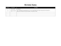 5
5 -
 6
6 -
 7
7 -
8
-
9
-
10
-
11
-
12
-
13
-
14
-
15
-
16
-
17
-
18
-
19
-
20
-
21
-
22
-
23
-
24
-
25
-
26
-
27
-
28
-
29
-
30
-
31
-
32
-
33
-
34
-
35
-
36
-
37
-
38
-
39
-
40
-
41
-
42
-
43
-
44
-
45
-
46
-
47
-
48
-
49
-
50
-
51
-
52
-
53
-
54
-
55
-
56
-
57
-
58
-
59
-
60
-
61
-
62
-
63
-
64
-
65
-
66
-
67
-
68
-
69
-
70
-
71
-
72
-
73
-
74
-
75
-
76
-
77
-
78
-
79
-
80
-
81
-
82
-
83
-
84
-
85
-
86
-
87
-
88
-
89
-
90
-
91
-
92
-
93
-
94
-
95
-
96
-
97
-
98
-
99
-
100
-
101
-
102
-
103
-
104
-
105
-
106
-
107
-
108
-
109
-
110
-
111
-
112
-
113
-
114
-
115
-
116
-
117
-
118
-
119
-
120
-
121
-
122
-
123
-
124
-
125
-
126
-
127
-
128
-
129
-
130
-
131
-
132
-
133
-
134
-
135
-
136
-
137
-
138
-
139
-
140
-
141
-
142
-
143
-
144
-
145
-
146
-
147
-
148
-
149
-
150
-
151
-
152
-
153
-
154
-
155
-
156
-
157
-
158
-
159
-
160
-
161
-
162
-
163
-
164
-
165
-
166
-
167
-
168
-
169
-
170
-
171
-
172
-
173
-
174
-
175
-
176
-
177
-
178
-
179
-
180
-
181
-
182
-
183
-
184
-
185
-
186
-
187
-
188
-
189
-
190
-
191
-
192
-
193
-
194
-
195
-
196
-
197
-
198
-
199
-
200
-
201
-
202
-
203
-
204
-
205
-
206
-
207
-
208
-
209
-
210
-
211
-
212
-
213
-
214
-
215
-
216
-
217
-
218
-
219
-
220
-
221
-
222
-
223
-
224
-
225
-
226
-
227
-
228
-
229
-
230
-
231
-
232
-
233
-
234
-
235
-
236
-
237
-
238
-
239
-
240
-
241
-
242
-
243
-
244
-
245
-
246
-
247
-
248
-
249
-
250
-
251
-
252
-
253
-
254
-
255
-
256
-
257
-
258
 |
 |

EPSON Stylus PHOTO 2100/2200
Color Inkjet Printer
SEIJ01-016
®
SERVICE MANUAL