Epson LQ-1500 User Manual - Page 29
Switch1, Switch settings
 |
View all Epson LQ-1500 manuals
Add to My Manuals
Save this manual to your list of manuals |
Page 29 highlights
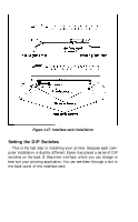
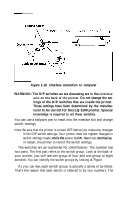
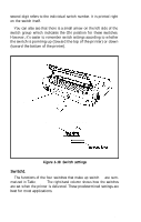
second digit refers to the individual switch number. It is printed right on the switch itself. You can also see that there is a small arrow on the left side of the switch group which indicates the ON position for these switches. However, it's easier to remember switch settings according to whether the switch is pointing up (toward the top of the printer) or down (toward the bottom of the printer). Interface Switch 1 Switch 2 Figure 1-19. Switch settings Switch1 The functions of the four switches that make up switch 1 are summarized in Table 1-1. The right-hand column shows how the switches are set when the printer is delivered. These predetermined settings are best for most applications. 21
-
 1
1 -
2
-
3
-
4
-
5
-
6
-
7
-
8
-
9
-
10
-
11
-
12
-
13
-
14
-
15
-
16
-
17
-
18
-
19
-
20
-
21
-
22
-
23
-
 24
24 -
 25
25 -
 26
26 -
 27
27 -
 28
28 -
 29
29 -
 30
30 -
 31
31 -
 32
32 -
 33
33 -
 34
34 -
35
-
36
-
37
-
38
-
39
-
40
-
41
-
42
-
43
-
44
-
45
-
46
-
47
-
48
-
49
-
50
-
51
-
52
-
53
-
54
-
55
-
56
-
57
-
58
-
59
-
60
-
61
-
62
-
63
-
64
-
65
-
66
-
67
-
68
-
69
-
70
-
71
-
72
-
73
-
74
-
75
-
76
-
77
-
78
-
79
-
80
-
81
-
82
-
83
-
84
-
85
-
86
-
87
-
88
-
89
-
90
-
91
-
92
-
93
-
94
-
95
-
96
-
97
-
98
-
99
-
100
-
101
-
102
-
103
-
104
-
105
-
106
-
107
-
108
-
109
-
110
-
111
 |
 |
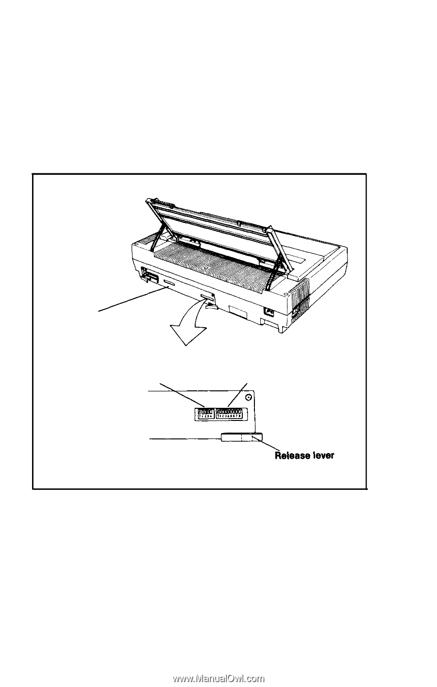
second digit refers to the individual switch number. It is printed right
on the switch itself.
You can also see that there is a small arrow on the left side of the
switch group which indicates the ON position for these switches.
However, it’s easier to remember switch settings according to whether
the switch is pointing up (toward the top of the printer) or down
(toward the bottom of the printer).
Interface
Switch 1
Switch 2
Figure 1-19. Switch settings
Switch1
The functions of the four switches that make up switch
1
are sum-
marized in Table
1-1.
The right-hand column shows how the switches
are set when the printer is delivered. These predetermined settings are
best for most applications.
21