Fluke 125B/S Calibration Guide - Page 7
List of s
 |
View all Fluke 125B/S manuals
Add to My Manuals
Save this manual to your list of manuals |
Page 7 highlights
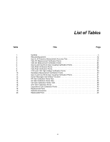
List of Figures Figure Title Page 1. Max. Input Voltage vs. Frequency for BB120 and STL120-IV 11 2. Safe Handling: Max. Voltage Between Test Tool Reference and Earth Ground 11 3. Test Tool Input A to Calibrator Scope Output 50 15 4. Test Tool Input B to Calibrator Scope Output 50 17 5. Test Tool Input A-B to Calibrator Scope Output 19 6. Test Tool Input A-B to Calibrator Normal Output 22 7. Bargraph Harmonics 28 8. Test Tool Input A-B to Calibrator Normal Output for >300 V 28 9. Test Tool Input A to Calibrator Normal Output 4-Wire 30 10. HF Gain Calibration Input Connections 35 11. Volt Gain Calibration Input Connections
-
 1
1 -
 2
2 -
 3
3 -
 4
4 -
 5
5 -
 6
6 -
 7
7 -
 8
8 -
 9
9 -
 10
10 -
 11
11 -
 12
12 -
13
-
14
-
15
-
16
-
17
-
18
-
19
-
20
-
21
-
22
-
23
-
24
-
25
-
26
-
27
-
28
-
29
-
30
-
31
-
32
-
33
-
34
-
35
-
36
-
37
-
38
-
39
-
40
-
41
-
42
-
43
-
44
-
45
-
46
-
47
-
48
-
49
-
50
-
51
-
52
-
53
-
54
 |
 |

v
Figure
Title
Page
1.
Max. Input Voltage vs. Frequency for BB120 and STL120-IV. . . . . . . . . . . . . . . . . . . . . . . . . . .11
2.
Safe Handling: Max. Voltage Between Test Tool Reference and Earth Ground. . . . . . . . . . . . .11
3.
Test Tool Input A to Calibrator Scope Output 50
Ω . . . . . . . . . . . . . . . . . . . . . . . . . . . . . . . . . . . . . . . . . . . 15
4.
Test Tool Input B to Calibrator Scope Output 50
Ω . . . . . . . . . . . . . . . . . . . . . . . . . . . . . . . . . . . . . . . . . . . 17
5.
Test Tool Input A-B to Calibrator Scope Output . . . . . . . . . . . . . . . . . . . . . . . . . . . . . . . . . . . . .19
6.
Test Tool Input A-B to Calibrator Normal Output. . . . . . . . . . . . . . . . . . . . . . . . . . . . . . . . . . . . .22
7.
Bargraph Harmonics . . . . . . . . . . . . . . . . . . . . . . . . . . . . . . . . . . . . . . . . . . . . . . . . . . . . . . . . . .28
8.
Test Tool Input A-B to Calibrator Normal Output for >300 V . . . . . . . . . . . . . . . . . . . . . . . . . . . .28
9.
Test Tool Input A to Calibrator Normal Output 4-Wire. . . . . . . . . . . . . . . . . . . . . . . . . . . . . . . . .30
10.
HF Gain Calibration Input Connections . . . . . . . . . . . . . . . . . . . . . . . . . . . . . . . . . . . . . . . . . . . .35
11.
Volt Gain Calibration Input Connections <300 V . . . . . . . . . . . . . . . . . . . . . . . . . . . . . . . . . . . . .37
12.
Four-Wire Ohms Calibration Connections. . . . . . . . . . . . . . . . . . . . . . . . . . . . . . . . . . . . . . . . . .38
13.
Capacitance Gain Calibration Input Connections . . . . . . . . . . . . . . . . . . . . . . . . . . . . . . . . . . . .39
14.
Battery Replacement/Charge . . . . . . . . . . . . . . . . . . . . . . . . . . . . . . . . . . . . . . . . . . . . . . . . . . .42
List of Figures