Fluke 28IIEX Fluke 28IIEx User Manual
Fluke 28IIEX Manual
 |
View all Fluke 28IIEX manuals
Add to My Manuals
Save this manual to your list of manuals |
Fluke 28IIEX manual content summary:
- Fluke 28IIEX | Fluke 28IIEx User Manual - Page 1
28 II Ex True-rms Digital Multimeter November 2011 © 2011 Fluke Corporation. All rights reserved. Specifications are subject to change without notice. All product names are trademarks of their respective companies. Users Manual - Fluke 28IIEX | Fluke 28IIEx User Manual - Page 2
to extend any other warranty on Fluke's behalf. To obtain service during the warranty period, contact your nearest Fluke authorized service center to obtain return authorization information, then send the product to that Service Center with a description of the problem. THIS WARRANTY IS YOUR ONLY - Fluke 28IIEX | Fluke 28IIEx User Manual - Page 3
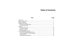
Table of Contents Title Page Introduction ...1 How to Contact Fluke ...1 Safety Information ...2 EX Safety Information ...2 Errors and Load Restrictions 6 Ex-Certification Data 7 Features ...9 Automatic Power-Off 15 Input Alert™ Feature 15 Power-Up Options ...16 How to Make Measurements 17 - Fluke 28IIEX | Fluke 28IIEx User Manual - Page 4
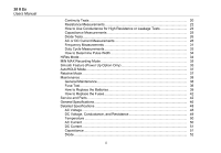
28 II Ex Users Manual Continuity Tests ...20 Resistance Measurements 22 How to Use Conductance for High Resistance or Leakage Tests 24 Capacitance Measurements 25 Diode Tests...26 AC or DC Current Measurements 28 39 How to Replace the Fuses 42 Service and Parts ...42 General Specifications 46 - Fluke 28IIEX | Fluke 28IIEx User Manual - Page 5
Contents (continued) Frequency ...52 Frequency Counter Sensitivity and Trigger Levels 52 Duty Cycle (Vdc and mVdc 53 Input Characteristics 53 MIN MAX Recording 54 iii - Fluke 28IIEX | Fluke 28IIEx User Manual - Page 6
28 II Ex Users Manual iv - Fluke 28IIEX | Fluke 28IIEx User Manual - Page 7
List of Tables Table Title Page 1. Symbols...8 2. Inputs ...9 3. Rotary Switch Positions...10 4. Pushbuttons ...11 5. Display Features ...13 6. Power-Up Options ...16 7. Functions and Trigger Levels for Frequency Measurements 32 8. MIN MAX Functions ...36 9. Approved Batteries ...40 10. - Fluke 28IIEX | Fluke 28IIEx User Manual - Page 8
28 II Ex Users Manual vi - Fluke 28IIEX | Fluke 28IIEx User Manual - Page 9
List of Figures Figure Title Page 1. Display Features ...13 2. AC and DC Voltage Measurements 17 3. Low-Pass Filter...19 4. Continuity Tests...21 5. Resistance Measurements ...23 6. Capacitance Measurements 25 7. Diode Tests ...27 8. Current Measurements...29 9. Components of Duty Cycle - Fluke 28IIEX | Fluke 28IIEx User Manual - Page 10
28 II Ex Users Manual viii - Fluke 28IIEX | Fluke 28IIEx User Manual - Page 11
Product. The 28 II Ex Digital Multimeter (the instructions. Read the entire Users Manual before you use the Product. How to Contact Fluke To contact Fluke, call one of the following telephone numbers: • Technical Support USA: 1-800-44-FLUKE (1-800443-5853) • Calibration/Repair USA: 1-888-99-FLUKE - Fluke 28IIEX | Fluke 28IIEx User Manual - Page 12
28 II Ex Users Manual Safety Information The Product complies with: • ISA-82.02.01 • CAN/CSA- Product, obey all instructions and warnings contained in this manual. EX Safety Information Note Go to www.ecom-ex.com or www.fluke.com download the EC declaration of conformity and Ex certificate for this - Fluke 28IIEX | Fluke 28IIEx User Manual - Page 13
the Fuses" section for a list of approved fuses. • Use the Product only when the specified connection values are met. True-rms Digital Multimeter EX Safety Information • After you use the Product on a nonintrinsically safe protected circuit, wait 3 minutes before you take the Product into an - Fluke 28IIEX | Fluke 28IIEx User Manual - Page 14
28 II Ex Users Manual WX Warning To prevent personal injury in mining hazardous areas: • Avoid ) to prevent shock and arc blast injury where hazardous live conductors are exposed • See the "EX Safety Information" section for additional warnings on Product use in hazardous areas. 4 • Use the Product - Fluke 28IIEX | Fluke 28IIEx User Manual - Page 15
and earth ground. • Do not touch the probes to a voltage source when the test leads are connected to the current terminals. True-rms Digital Multimeter EX Safety Information • Connect the common test lead before the live test lead and remove the live test lead before the common test lead. • Replace - Fluke 28IIEX | Fluke 28IIEx User Manual - Page 16
28 II Ex Users Manual WCaution To avoid possible damage to the Product or to the equipment that the safety or integrity of this Product is compromised, remove it from operation and the Ex-hazardous areas immediately. Also, do whatever is necessary to prevent Product operation by others until the - Fluke 28IIEX | Fluke 28IIEx User Manual - Page 17
V C0 = 1000 μF I0 = 9.7 μA L0 = 1000 mH P0 = 0 mWH Ui = 65 V Ci = negligible Ii = 5 A Li = negligible True-rms Digital Multimeter EX Safety Information mA/μA Jack U0 = 1.94 V Ui = 65 V C0 = 1000 μF Ci = negligible I0 = 9.7 μA Ii = Internally limited by a 440 mA fuse L0 = 1000 mH Li = negligible P0 - Fluke 28IIEX | Fluke 28IIEx User Manual - Page 18
28 II Ex Users Manual AC (Alternating Current) Table 1. Symbols J Earth ground DC (Direct Current) X Hazardous voltage I Fuse P Conforms to European Union directives. W Risk of Danger. Important information. See Manual. Battery. Low battery when displayed. T Diode Double - Fluke 28IIEX | Fluke 28IIEx User Manual - Page 19
Features Tables 2 through 5 show the features of the Product. Table 2. Inputs 1 True-rms Digital Multimeter Features 2 Item 3 4 Terminal A COM Description grt01.eps Input for 0 A to 10.00 A current (10 A to 20 A overload for 30 seconds maximum), current frequency, and duty - Fluke 28IIEX | Fluke 28IIEx User Manual - Page 20
28 II Ex Users Manual Switch Position Any Position J L M N O P Q Table 3. Rotary Switch Positions Function When the Product is turned on, the Product model number briefly shows on the display. AC - Fluke 28IIEX | Fluke 28IIEx User Manual - Page 21
Button (Yellow) C D Switch Position Any position M Any position MIN MAX recording Frequency counter Table 4. Pushbuttons True-rms Digital Multimeter Features Function Set to capacitance Set to temperature Turn on ac low-pass filter Set dc or ac current Set dc or ac current Change - Fluke 28IIEX | Fluke 28IIEx User Manual - Page 22
28 II Ex Users Manual Button E H Switch Position Continuity N MIN MAX recording Hz, Duty Cycle Any position F (Relative mode) G Any position Any position Any position except diode test Table 4. Pushbuttons ( - Fluke 28IIEX | Fluke 28IIEx User Manual - Page 23
Hz/duty cycle triggering. X The continuity beeper is on. W Relative (REL) mode is active. Smoothing is active. True-rms Digital Multimeter Features Number Feature Indication Negative measurement. In relative - mode, this sign shows that the input is less than the stored - Fluke 28IIEX | Fluke 28IIEx User Manual - Page 24
28 II Ex Users Manual Table 5. Display Features (cont.) Number Feature Indication Low battery. XW Warning: To selected range Autorange mode. Automatically Auto selects the range with the best resolution. Manual Manual range mode HiRes High resolution (Hi Res) mode HiRes=19,999 14 - Fluke 28IIEX | Fluke 28IIEx User Manual - Page 25
electrical charge is on the capacitor under test. CAL Err Invalid calibration data. Calibrate Product. EEPr Err Invalid EEPROM data. Have the Product serviced. 0PEn Open thermocouple detected. F2_ LEAd Invalid model. Have the Product serviced. W Test lead alert. Shows when the test leads are in - Fluke 28IIEX | Fluke 28IIEx User Manual - Page 26
28 II Ex Users Manual Power-Up Options To set a power-up option, push a button down while and prompts for a password. The Product shows "CAL" in the display and enters calibration mode. See 28 II Ex Calibration Information. C Turns on the smoothing feature. The Product reads "'---" until C is - Fluke 28IIEX | Fluke 28IIEx User Manual - Page 27
V. The select the 600.0 mV dc range, turn the rotary switch to mV. Refer to Figure 2 to measure ac or dc voltage. True-rms Digital Multimeter How to Make Measurements AC Voltage Switch Box V DC Voltage mV V + grt02.eps Figure 2. AC and DC Voltage Measurements 17 - Fluke 28IIEX | Fluke 28IIEx User Manual - Page 28
28 II Ex Users Manual When you measure voltage, the Product puts approximately 10-MΩ (10,000,000 because the input protection circuits are disabled. Zero Input Behavior of True-rms Meters True-rms meters accurately measure distorted waveforms, but when the input leads are shorted together in the - Fluke 28IIEX | Fluke 28IIEx User Manual - Page 29
the filter. Note When the low-pass filter is selected, the Product goes to manual range mode. Push to set the range. The Product does not autorange with between degrees Celsius (°C) or degrees Fahrenheit (°F). True-rms Digital Multimeter How to Make Measurements W Caution To prevent damage to - Fluke 28IIEX | Fluke 28IIEx User Manual - Page 30
28 II Ex Users Manual Continuity Tests WCaution To prevent damage to the Product or to the equipment under test, disconnect circuit power and discharge all high-voltage capacitors before - Fluke 28IIEX | Fluke 28IIEx User Manual - Page 31
For in-circuit tests, turn circuit power off. Activates continuity beeper ON (closed) True-rms Digital Multimeter How to Make Measurements OFF (open) Figure 4. Continuity Tests grt03.eps 21 - Fluke 28IIEX | Fluke 28IIEx User Manual - Page 32
28 II Ex Users Manual Resistance Measurements WCaution To prevent damage to the Product or to the equipment under test, disconnect the power and discharge all high-voltage capacitors before - Fluke 28IIEX | Fluke 28IIEx User Manual - Page 33
In-Circuit Resistance Measurements Circuit Power OFF True-rms Digital Multimeter How to Make Measurements Isolating a Potentiometer 1 3 2 Disconnect 1 2 3 Isolating a Resistor Figure 5. Resistance Measurements Disconnect grt04.eps 23 - Fluke 28IIEX | Fluke 28IIEx User Manual - Page 34
28 II Ex Users Manual How to Use Conductance for High Resistance or Leakage Tests Conductance, the inverse of resistance, is a measure of how easily current goes through a circuit. High - Fluke 28IIEX | Fluke 28IIEx User Manual - Page 35
the remaining capacitance of the Product and leads. Note When a capacitor under test has too much electrical charge, the display shows "diSC". True-rms Digital Multimeter How to Make Measurements Select Capacitance + + Figure 6. Capacitance Measurements grt05.eps 25 - Fluke 28IIEX | Fluke 28IIEx User Manual - Page 36
28 II Ex Users Manual Diode Tests WCaution To prevent damage to the Product or to the equipment under test, disconnect circuit power and discharge all high-voltage capacitors before - Fluke 28IIEX | Fluke 28IIEx User Manual - Page 37
Typical Reading Forward Bias + Single Beep Bad Diode Open True-rms Digital Multimeter How to Make Measurements Reverse Bias + Bad Diode Shorted or Figure 7. Diode Tests grt06.eps 27 - Fluke 28IIEX | Fluke 28IIEx User Manual - Page 38
28 II Ex Users Manual AC or DC Current Measurements XWWarning To prevent electric shock or personal injury, do not try an in-circuit current measurement where the open-circuit /μA terminal only if you are sure the current is less than 400 mA continuously or less than 600 mA for 18 hours or less. 28 - Fluke 28IIEX | Fluke 28IIEx User Manual - Page 39
1 4 mA A 3 A 2 Circuit Power: OFF to connect meter. ON for measurement. OFF to disconnect meter. True-rms Digital Multimeter How to Make Measurements Total Current to Circuit 5 Current Through One Component Figure 8. Current Measurements 5 grt07.eps 29 - Fluke 28IIEX | Fluke 28IIEx User Manual - Page 40
28 II Ex Users Manual 3. If you use the A terminal, set the rotary switch to mA/A. If Product is set up correctly, do a fuse test. See the "Fuse Test" section. • A current meter drops a small voltage across itself, which could change circuit operation. You can calculate this burden voltage with the - Fluke 28IIEX | Fluke 28IIEx User Manual - Page 41
Less than 0.5 Hz, the display can be unstable. True-rms Digital Multimeter How to Make Measurements Some guidelines for frequency measurements are: • If signal can be below or near the trigger level. To correct these problems, go to a lower range, which increases the sensitivity of the Product - Fluke 28IIEX | Fluke 28IIEx User Manual - Page 42
28 II Ex Users Manual Function Table 7. Functions and Trigger Levels for Frequency Measurements Range Approximate Trigger Level Typical Application 6 V, 60 V, ±5 % of scale Most signals. 600 V, 1000 V 600 mV ±30 - Fluke 28IIEX | Fluke 28IIEx User Manual - Page 43
a duty cycle measurement. To measure duty cycle, set up the Product to measure frequency. Then push G a second time. As with the True-rms Digital Multimeter How to Make Measurements frequency function, Push E to change the slope for the counter. For 5-V logic signals, use the 6-V dc range. For 12 - Fluke 28IIEX | Fluke 28IIEx User Manual - Page 44
28 II Ex Users Manual How to Determine Pulse Width For a periodic waveform (its pattern repeats at equal time intervals), you can find the time that the signal is high - Fluke 28IIEX | Fluke 28IIEx User Manual - Page 45
to smooth out unstable inputs, calculate power consumption, or to get a percentage of time estimate on how long a circuit is on. True-rms Digital Multimeter MIN MAX Recording Mode Min Max records the signal extremes that are longer than 100 ms. Peak records the signal extremes that are longer than - Fluke 28IIEX | Fluke 28IIEx User Manual - Page 46
28 II Ex Users Manual Button (while in MIN MAX mode) E PEAK MIN MAX D (hold for 1 second) Table 8. MIN MAX Functions MIN MAX Function Enter MIN MAX recording mode. The - Fluke 28IIEX | Fluke 28IIEx User Manual - Page 47
a new, stable measurement is sensed, the Product beeps and shows the new measurement. To start or exit AutoHOLD mode, push D. True-rms Digital Multimeter AutoHOLD Mode Relative Mode When you set relative mode (F),the Product zeros the display and stores the current measurement as the reference for - Fluke 28IIEX | Fluke 28IIEx User Manual - Page 48
28 II Ex Users Manual Maintenance XWWarning To prevent electrical shock or personal injury, have the Product repaired by ECOM Instruments GmbH or an ECOM authorized service of the terminals. It is recommended that the Product be calibrated by Fluke in two-year intervals. Fuse Test As shown in Figure - Fluke 28IIEX | Fluke 28IIEx User Manual - Page 49
: 0.995 kΩ to 1.005 kΩ Replace fuse: OL Touch top half of input contacts Good 11 A fuse: 0.0 Ω to 0.5 Ω Replace fuse: OL True-rms Digital Multimeter Maintenance How to Replace the Batteries Replace the batteries with three AAA batteries (NEDA 24A IEC LR03). XWWarning To prevent electrical shock or - Fluke 28IIEX | Fluke 28IIEx User Manual - Page 50
28 II Ex Users Manual Replace the batteries as follows, refer to Figure 11: 1. Turn the rotary switch to OFF and remove the test leads from the terminals. 2. Remove the - Fluke 28IIEX | Fluke 28IIEx User Manual - Page 51
1 3 2 True-rms Digital Multimeter Maintenance 5 4 Figure 11. Battery and Fuse Replacement grt10.eps 41 - Fluke 28IIEX | Fluke 28IIEx User Manual - Page 52
28 II Ex Users Manual How to Replace the Fuses Examine or replace the fuses in Replace the Batteries" section above to replace the battery door. Service and Parts If the Product fails, examine the batteries and fuses. Refer to this manual to make sure the Product is used correctly. Replacement parts - Fluke 28IIEX | Fluke 28IIEx User Manual - Page 53
II Ex Holster 28 II Ex Battery Door Assembly Alligator Clip, Black Alligator Clip, Red Test Lead Set Integrated DMM Temperature Probe 28 II Ex Users Manual CD 28 II Ex Getting Started Manual W To ensure safety, use exact replacement only. True-rms Digital Multimeter Service and Parts Qty. Fluke - Fluke 28IIEX | Fluke 28IIEx User Manual - Page 54
Battery Door Gasket Fuse 11 A, 1000 V, Fast 44 Battery AAA 1.5 V Fuse Assembly *Contains 440 mA Fuse 28 II Ex Users Manual CD 28 II Ex Getting Started Manual Figure 12. Replacement Parts AC172 Alligator Clips 28 II Ex Holster TL175 Test Lead Set 80BK-A Integrated DMM Temperature Probe grt11.eps - Fluke 28IIEX | Fluke 28IIEx User Manual - Page 55
True-rms Digital Multimeter Service and Parts Table 11. Accessories Item Description AC172 in this table are approved for use in explosive hazardous environments. Fluke accessories are available from an authorized Fluke distributor. [1] W Warning - To prevent personal injury or property - Fluke 28IIEX | Fluke 28IIEx User Manual - Page 56
28 II Ex Users Manual General Specifications Maximum voltage between any terminal and earth ground counts, updates 4/sec (19,999 counts in high-resolution mode). Altitude Operating 2,000 meters Storage 10,000 meters Temperature Operating 15 °C to 50 °C Storage 55 °C to +85 °C (without battery - Fluke 28IIEX | Fluke 28IIEx User Manual - Page 57
True-rms Digital Multimeter General Specifications Electromagnetic Compatibility (EN 61326-1:2005).....In 400 hrs typical without backlight (Alkaline) Vibration Per MIL-PRF-28800 for a Class 2 instrument Shock 1 Meter drop per IEC 61010 (3 Meter drop with holster) Size (H x W x L 4.57 cm x 10.0 cm - Fluke 28IIEX | Fluke 28IIEx User Manual - Page 58
28 II Ex Users Manual Detailed Specifications For all detailed specifications: Accuracy is specified for 2 years after calibration, at operating temperatures of 18 °C to 28 °C, with relative humidity at 0 % to 80 %. Accuracy specifications take the form of ±([% of Reading] + [Number of least- - Fluke 28IIEX | Fluke 28IIEx User Manual - Page 59
True-rms Digital Multimeter Detailed Specifications DC Voltage, Conductance, and Resistance Function Range Resolution Accuracy mV dc V dc 600.0 mV 6.000 V 60.00 V 600.0 V 1000 V 600.0 Ω 0.1 mV 0.001 V 0.01 V 0.1 V 1 V 0.1 Ω ±(0.1 % + 1) ±(0. - Fluke 28IIEX | Fluke 28IIEx User Manual - Page 60
28 II Ex Users Manual Temperature Range Resolution Accuracy [1,2] -200 °C to +1090 °C 0.1 °C ±(1.0 % + 10) -328 °F to +1994 °F 0.1 °F ±(1.0 % + 18) [1] Does not include error of the thermocouple probe. [2] Accuracy specification assumes ambient temperature - Fluke 28IIEX | Fluke 28IIEx User Manual - Page 61
True-rms Digital Multimeter Detailed Specifications DC Current Function Range Resolution Burden Voltage Accuracy μA dc 600.0 μA 6000 μA 0.1 μA 1 μA 100 μV/μA 100 μV/μA ±(0.2 % + 4) ±(0.2 % + 2) mA dc 60.00 mA 400.0 mA [1] 0.01 mA 0.1 mA 1.8 - Fluke 28IIEX | Fluke 28IIEx User Manual - Page 62
28 II Ex Users Manual Diode 2.000 V Range 0.001 V Resolution Frequency Range 199.99 Hz 1999.9 Hz 19.999 kHz 199.99 kHz >200 kHz 0.01 Hz 0.1 Hz 0.001 kHz 0. - Fluke 28IIEX | Fluke 28IIEx User Manual - Page 63
True-rms Digital Multimeter Detailed Specifications Duty Cycle (Vdc and mVdc) Range Accuracy 0.0 % to 99.9 % [1] Within ± (0.2 % per kHz + 0.1 %) for rise times 2 μs. Pulse width - Fluke 28IIEX | Fluke 28IIEx User Manual - Page 64
28 II Ex Users Manual MIN MAX Recording Nominal Response 100 ms to 80 % (dc functions) 120 ms to 80 % (ac functions) 250 μs (peak) [1] [1] For 6 V range: 1 ms Accuracy Specified accuracy ±
-
 1
1 -
 2
2 -
 3
3 -
 4
4 -
 5
5 -
 6
6 -
 7
7 -
8
-
9
-
10
-
11
-
12
-
13
-
14
-
15
-
16
-
17
-
18
-
19
-
20
-
21
-
22
-
23
-
24
-
25
-
26
-
27
-
28
-
29
-
30
-
31
-
32
-
33
-
34
-
35
-
36
-
37
-
38
-
39
-
40
-
41
-
42
-
43
-
44
-
45
-
46
-
47
-
48
-
49
-
50
-
51
-
52
-
53
-
54
-
55
-
56
-
57
-
58
-
59
-
60
-
61
-
62
-
63
-
64
 |
 |

November 2011
© 2011 Fluke Corporation. All rights reserved. Specifications are subject to change without notice.
All product names are trademarks of their respective companies.
28 II Ex
True-rms Digital Multimeter
Users Manual