Fluke 28IIEX Fluke 28IIEx User Manual - Page 36
Diode Tests, capacitors before you do a diode test.
 |
View all Fluke 28IIEX manuals
Add to My Manuals
Save this manual to your list of manuals |
Page 36 highlights
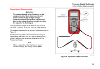
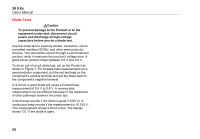
28 II Ex Users Manual Diode Tests WCaution To prevent damage to the Product or to the equipment under test, disconnect circuit power and discharge all high-voltage capacitors before you do a diode test. Use the diode test to examine diodes, transistors, silicon controlled rectifiers (SCRs), and other semiconductor devices. This test sends current through a semiconductor junction, while it measures the junction's voltage drop. A good silicon junction drops between 0.5 V and 0.8 V. To do an out of circuit diode test, set up the Product as shown in Figure 7. For forward-bias measurements on a semiconductor component, put the red test lead on the component's positive terminal and put the black lead on the component's negative terminal. In a circuit, a good diode will cause a forward-bias measurement of 0.5 V to 0.8 V. A reverse-bias measurement can be different because of the resistance of other pathways between the probe tips. A short beep sounds if the diode is good (
-
 1
1 -
2
-
3
-
4
-
5
-
6
-
7
-
8
-
9
-
10
-
11
-
12
-
13
-
14
-
15
-
16
-
17
-
18
-
19
-
20
-
21
-
22
-
23
-
24
-
25
-
26
-
27
-
28
-
29
-
30
-
 31
31 -
 32
32 -
 33
33 -
 34
34 -
 35
35 -
 36
36 -
 37
37 -
 38
38 -
 39
39 -
 40
40 -
 41
41 -
42
-
43
-
44
-
45
-
46
-
47
-
48
-
49
-
50
-
51
-
52
-
53
-
54
-
55
-
56
-
57
-
58
-
59
-
60
-
61
-
62
-
63
-
64
 |
 |
