Fluke 8845A FE 8845A & 8846A Users Manual
Fluke 8845A Manual
 |
View all Fluke 8845A manuals
Add to My Manuals
Save this manual to your list of manuals |
Fluke 8845A manual content summary:
- Fluke 8845A | FE 8845A & 8846A Users Manual - Page 1
® 8845A/8846A Digital Multimeter Users Manual July 2006 © 2006 Fluke Corporation. All rights reserved. All product names are trademarks of their respective companies. - Fluke 8845A | FE 8845A & 8846A Users Manual - Page 2
normal use and service. The warranty period is one year and begins on the date of shipment. Parts, product repairs, and services are warranted for 90 days. This warranty extends only to the original buyer or end-user customer of a Fluke authorized reseller, and does not apply to fuses, disposable - Fluke 8845A | FE 8845A & 8846A Users Manual - Page 3
10 Remote Interfaces 1-10 Warranty ...1-10 Electrical Specifications 1-10 DC Voltage Specifications 1-10 AC Voltage Specifications 1-11 Resistance ...1-13 DC Current ...1-15 AC Current ...1-16 Frequency ...1-18 Capacitance (8846A Only 1-19 Temperature (8846A only 1-19 Continuity ...1-19 i - Fluke 8845A | FE 8845A & 8846A Users Manual - Page 4
8845A/8846A Users Manual 2 3 Diode Test ...1-20 Measurement Rates 1-20 Preparing the Meter for Operation 2-1 Introduction...2-3 Unpacking and Inspecting the Meter 2-3 Contacting Fluke 2-3 Storing and Shipping the Meter 2-3 Power Considerations 2-3 Selecting the Line Voltage Meter's Range 3-7 - Fluke 8845A | FE 8845A & 8846A Users Manual - Page 5
the Meter's Calibration Date 3-22 Resetting the Meter's Default Settings 3-22 4 Making Measurements 4-1 Introduction...4-3 Selecting Function Modifiers 4-3 Activating the Secondary Display 4-3 Measuring Voltage 4-4 Measuring DC Voltage 4-4 Measuring AC Voltage 4-5 Measuring Frequency - Fluke 8845A | FE 8845A & 8846A Users Manual - Page 6
8845A/8846A Users Manual iv - Fluke 8845A | FE 8845A & 8846A Users Manual - Page 7
Symbols 1-6 1-3. Volatile Memory Space 1-6 1-4. Non-volatile Memory Space 1-7 1-3. Accessories...1-7 2-1. Line Voltage to Fuse Rating 2-5 2-2. Line Power Cord Types Available from Fluke 2-7 3-1. Front-Panel Controls and Connectors 3-3 3-2. Display Elements 3-5 3-3. Rear-Panel Conncetors - Fluke 8845A | FE 8845A & 8846A Users Manual - Page 8
8845A/8846A Users Manual vi - Fluke 8845A | FE 8845A & 8846A Users Manual - Page 9
Page 2-1. Replacing the Line Fuse 2-5 2-2. Replacing the Current Input Fuses 2-6 2-3. Line Power Cords Types Available from Fluke 2-7 2-4. Bail Adjustment and Removal 2-8 3-1. TrendPlot Display 3-14 3-2. Histogram Display 3-14 4-1. Input Connections for Voltage, Resistance, and Frequency - Fluke 8845A | FE 8845A & 8846A Users Manual - Page 10
8845A/8846A Users Manual viii - Fluke 8845A | FE 8845A & 8846A Users Manual - Page 11
10 Remote Interfaces 1-10 Warranty ...1-10 Electrical Specifications 1-10 DC Voltage Specifications 1-10 AC Voltage Specifications 1-11 Resistance ...1-13 DC Current ...1-15 AC Current ...1-16 Frequency ...1-18 Capacitance (8846A Only 1-19 Temperature (8846A only 1-19 Continuity ...1-19 1-1 - Fluke 8845A | FE 8845A & 8846A Users Manual - Page 12
8845A/8846A Users Manual Diode Test ...1-20 Measurement Rates 1-20 1-2 - Fluke 8845A | FE 8845A & 8846A Users Manual - Page 13
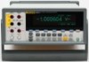
The 8845A and 8846A are 6-1/2 digit, dual-display multimeters designed for bench-top, field service, and system applications. Their full complement of measurement functions plus its RS-232, IEEE 488, and Ethernet Remote Interfaces makes these multimeters ideal candidates for precision manual - Fluke 8845A | FE 8845A & 8846A Users Manual - Page 14
8845A and 8846A Digital Multimeters (hereafter referred to as the Meter). It contains all of the information a new user will need to operate the Meter effectively. The manual is divided into the following chapters: Chapter 1 "Introduction and Specifications" provides information on how to safely use - Fluke 8845A | FE 8845A & 8846A Users Manual - Page 15
removed or the case open. • Use caution when working with voltages above 30 V ac rms, 42 V ac peak, or 42 V dc. These voltages pose a shock hazard. • Use only the replacement fuse(s) specified by the manual. • Use the proper terminals, function, and range for your measurements. • Do not operate - Fluke 8845A | FE 8845A & 8846A Users Manual - Page 16
8845A/8846A Users Manual Symbols Table 1-2 is a list of safety and electrical symbols that appear on the Meter or in this manual. Table 1-2. Safety and Electrical Symbols Symbol Description W Risk of danger. Important information. See manual X Hazardous voltage. Voltage > 30 V dc or ac - Fluke 8845A | FE 8845A & 8846A Users Manual - Page 17
and 8846A. Table 1-5. Accessories Model/Fluke PN TL71 6303 6730 5940 5143 6275 6344 884X-Short 884X-Case Description Premium Test Lead Set Kelvin Probes Kelvin Lead Set with Alligator Clips Kelvin clip set SMD Test Tweezer Leads Precision Electronic Probe Set Basic Electronic DMM Test Set 4-Wire - Fluke 8845A | FE 8845A & 8846A Users Manual - Page 18
8845A/8846A Users Manual Table 1-3. Accessories (cont) Model/Fluke PN Description TL910 TL80A TL2X4W-PT 1256480 1258910 1256990 1024830 2426684 1028820 1259170 1258730 1259340 2441827 1540600 Precision Electronic Probe Set Basic Electronic DMM Test Set 2X4 Wire Ohms Test Lead 2X4 Wire Ohms SMD - Fluke 8845A | FE 8845A & 8846A Users Manual - Page 19
Introduction and Specifications General Specifications General Specifications Power Voltage 100 V comply with IEC 61326-1:2000-11 (EMC) when used with shielded communications cables. This Meter has shown susceptibity to to 450 MHz while in the 100 µA range. Triggering Samples per Trigger 1 to 50,000 - Fluke 8845A | FE 8845A & 8846A Users Manual - Page 20
V dc, 1000 V ac (8846A), 750 V ac (8845A), Diode, and 10 A ranges Remote Interfaces RS-232 (RS-232 to USB cable available to connect the Meter to a PC USB port. See accessories) IEEE 488.2 LAN Warranty One year Electrical Specifications Accuracy specifications are valid for 6½ digit mode after at - Fluke 8845A | FE 8845A & 8846A Users Manual - Page 21
AC Voltage specifications are for ac sinewave signals >5 % of range. For inputs from 1 % to 5 % of range and - Fluke 8845A | FE 8845A & 8846A Users Manual - Page 22
8845A/8846A Users Manual Input Characteristics Range 100 mV 1 V 10 V 100 V 1000 V Full Scale (6½ Digits) 100.0000 mV 1.000000 V 10.00000 V 100.0000 V 1,000.000 V 4½ Digits 10 µV 100 µV 1 mV 10 mV 100 mV Resolution 5½ Digits 1 µV 10 µV 100 µV 1 mV 10 mV 6½ Digits 100 nV 1 µV 10 µV 100 µV 1 mV - Fluke 8845A | FE 8845A & 8846A Users Manual - Page 23
1 Introduction and Specifications Electrical Specifications 8845A Accuracy Accuracy is given as ± (% measurement + % of range) Range Frequency (Hz) 24 Hour Resistance Specifications are for 4-wire resistance function, 2 x 4-wire resistance, or 2-wire resistance with zero. If zero is not used, add - Fluke 8845A | FE 8845A & 8846A Users Manual - Page 24
8845A/8846A Users Manual 1-14 Max. Lead Resistance (4-wire ohms 10 % of range per lead for 100 Ω, 1 kΩ ranges. 1 kΩ per lead on all other ranges. Input Protection 1000 V on all ranges. Input Characteristics Range Full Scale (6½ Digits) 10 Ω[1] 10.00000 Ω 100 Ω 100.0000 Ω 1 kΩ 1.000000 kΩ - Fluke 8845A | FE 8845A & 8846A Users Manual - Page 25
µA 10 µA 100 µA 100 µA 6½ Digits 100 pA 1 nA 10 nA 100 nA 1 µA 10 µA 10 µA Shunt Resistance (Ohms) Burden Voltage 100Ω 100Ω 1 Ω 1 Ω 0.01 Ω 0.01 Ω 0.01 Ω - Fluke 8845A | FE 8845A & 8846A Users Manual - Page 26
8845A/8846A Users Manual AC Current The following ac current specifications are for sinusoidal signals with amplitudes greater than 5 % of range. For inputs from 1% to 5 % of range, add an additional error of 0.1 % of range. Input Protection Tool accessible 11 A/1000 V and 440 mA/1000 V fuses. - Fluke 8845A | FE 8845A & 8846A Users Manual - Page 27
1 Introduction and Specifications Electrical Specifications 8846A Accuracy (cont) 3 A[1][2] 10 A[2] 3 - 5 Hz 5 - 10 Hz 10 Hz - 5 kHz 5 Part of 10 A range [2] Available only on front panel connectors 8845A Accuracy Accuracy is given as ± (% measurement + % of range) Range Frequency (Hz) 24 - Fluke 8845A | FE 8845A & 8846A Users Manual - Page 28
8845A/8846A Users Manual Frequency Gate Times Programmable to 1 s, 100 ms, and 10 ms. Measurement Method Flexible counting technique. AC-coupled input using the ac voltage measurement function. Settling Considerations When measuring frequency or period after a dc offset voltage change, errors - Fluke 8845A | FE 8845A & 8846A Users Manual - Page 29
Specifications Capacitance (8846A Only) Accuracy is stated as ±(% of measurement + % of range) Range Resolution 1 nF 1 pF 10 nF 10 pF 100 nF 100 pF 1 µF 1 nF 10 µF 10 nF 100 µF 100 nF 1 mF 1 µF 10 mF 10 µF 100 mF 100 µF [1] Stated accuracy is attained when Zero function is used - Fluke 8845A | FE 8845A & 8846A Users Manual - Page 30
8845A/8846A Users Manual Diode Test Test Current 100 µA or 1 mA Response Time 300 samples/sec with audible tone. Accuracy is given as ± (% measurements + % of range) Range Rates Function Digits Integration Time Setting 60 Hz (50 Hz) Measurements/Second[1] 8845A 8846A DC Volts, - Fluke 8845A | FE 8845A & 8846A Users Manual - Page 31
Page Introduction...2-3 Unpacking and Inspecting the Meter 2-3 Contacting Fluke 2-3 Storing and Shipping the Meter 2-3 Power Considerations 2-3 Selecting the Line Voltage 2-4 Replacing the Fuses 2-4 Line-Power Fuse 2-4 Current-Input Fuses 2-5 Connecting to Line Power 2-7 Turning Power-On - Fluke 8845A | FE 8845A & 8846A Users Manual - Page 32
8845A/8846A Users Manual 2-2 - Fluke 8845A | FE 8845A & 8846A Users Manual - Page 33
selecting the proper line voltage, connecting an appropriate line Fluke distributor or Service Center, call: USA: Canada: Europe: Japan: Singapore: Anywhere in the world: Service in USA: 1-888-44-FLUKE (1-888-443-5853) 1-800-36-FLUKE specification described in Chapter 1. If the Meter is shipped, use - Fluke 8845A | FE 8845A & 8846A Users Manual - Page 34
8845A/8846A Users Manual does not match the power the Meter will be plugged into, then the Meter's line voltage setting must be changed and the line fuse possibly replaced. Selecting the Line Voltage The Meter will operate on any one of four different input line voltages. The set line voltage is - Fluke 8845A | FE 8845A & 8846A Users Manual - Page 35
Table 2-1. Line Voltage to Fuse Rating Line Voltage Selection Fuse Rating Fluke Part No. user-replaceable fuses. • The 100 mA input is protected by a fuse (F2) rated at 440 mA, 1000 V (fast blow), 10,000 A minimum breaking capacity (Fluke Part No. 943121). • The 10 A input is protected by a fuse - Fluke 8845A | FE 8845A & 8846A Users Manual - Page 36
8845A/8846A Users Manual If the fuse is good, the Meter will read less than 1 Ω. If the fuse is blown, the Meter will read overload. To replace the Current Input fuses, 1. Turn the Meter off, unplug the power cord from the Meter, and remove all test leads. 2. Turn the Meter on its back. 3. Unscrew - Fluke 8845A | FE 8845A & 8846A Users Manual - Page 37
cord must be used, a protective fuse for that line voltage is installed. Connect the Meter to a properly grounded three-prong outlet. Type North America North America Universal Euro United Kingdom Switzerland Australia South Africa Table 2-2. Line Power Cord Types Available from Fluke Voltage - Fluke 8845A | FE 8845A & 8846A Users Manual - Page 38
8846A Users Manual Turning Power-On XW Warning To avoid electric shock, connect the Meter's power cord to a power receptacle with proper earth ground. A protective ground connection by way of the grounding conductor in the power cord is essential for safe operation. With the proper line voltage RANGE - Fluke 8845A | FE 8845A & 8846A Users Manual - Page 39
not apply solvents to the Meter. If the Meter requires cleaning, wipe it down with a cloth lightly dampened with water or a mild detergent. Do not use aromatic hydrocarbons, chlorinated solvents, or methanolbased fluids when wiping down the meter. 2-9 - Fluke 8845A | FE 8845A & 8846A Users Manual - Page 40
8845A/8846A Users Manual 2-10 - Fluke 8845A | FE 8845A & 8846A Users Manual - Page 41
3-6 Adjusting the Meter's Range 3-7 Navigating the Front-Panel 8846A Only 3-9 Enabling Automatic Input Impedance 3-9 Using the Analyze Functions 3-9 Collecting Statistics on Measurements 3-10 Testing Using Limits 3-11 Setting an Offset Value 3-12 Using MX+B 3-12 Using TrendPlot 3-13 Using - Fluke 8845A | FE 8845A & 8846A Users Manual - Page 42
8845A/8846A Users Manual Setting the Meter's Date and Time 3-21 Configuring the Remote Interface 3-22 Checking the Meter's Calibration Date 3-22 Resetting the Meter's Default Settings 3-22 3-2 - Fluke 8845A | FE 8845A & 8846A Users Manual - Page 43
commands through one of its communication interfaces or by manual manipulation of its front panel controls. This chapter explains the function and use II 300 V LO LO 1V FUSED 100 mA 10 A REAR FRONT 8846A 6-1/2 DIGIT PRECISION MULTIMETER BACK F1 F2 F3 F4 F5 RANGE DC V AC V DC I - Fluke 8845A | FE 8845A & 8846A Users Manual - Page 44
8845A/8846A Users Manual B Sense HI and LO connectors. Output connectors to source current for 4-wire Ohms measurements. Soft keys F1 through F5. Soft keys are used standby, the Meter will not respond to F remote or front-panel commands. When taken out of standby, the Meter sets itself to its - Fluke 8845A | FE 8845A & 8846A Users Manual - Page 45
is stored. Soft key key labels. Manual range mode selected. See "Adjusting the Meter's Range" section. The Meter is under remote control 6½ digits (-1999999 to 1999999), plus a decimal point. In the example shown above, the primary display shows measurement results for an ac voltage measurement. - Fluke 8845A | FE 8845A & 8846A Users Manual - Page 46
CONNECTED SERIAL TAG NO INTERNAL USER SERVICEABLE PARTS REFER SERVICE TO QUALIFIED SERVICE PERSONNEL N10140 FLUKE CORPORATION MADE IN USA www.fluke.com 9 8 7 6 5 caw05.eps Item A B C D E F G H I Description Line Power Cord connector Power Switch Fuse holder and power line voltage selector - Fluke 8845A | FE 8845A & 8846A Users Manual - Page 47
manual ranging. The presence or absence of MAN in the display indicates the Meter's range mode. All functions utilize these keys to control the Meter's range except continuity, diode test, temperature (8846A " and Chapter four's instructions on "Making Measurements", cover the use of the Meter's menu - Fluke 8845A | FE 8845A & 8846A Users Manual - Page 48
8845A/8846A Users Manual The soft key labels are updated with five choices. 4 DIGIT .02 PLC 5 DIGIT .2 PLC 5 DIGIT 1 PLC 6 DIGIT 10 PLC 6 DIGIT 100 PLC These choices determine the displayed resolution (4½, 5½, and 6½ digits and the amount of current and voltage used for Diode testing are adjustable. - Fluke 8845A | FE 8845A & 8846A Users Manual - Page 49
3 Front-Panel Operation Using the Analyze Functions Refer to the "Testing Continuity" section in Chapter 4 to test continuity. Setting the Diode Test Voltage and Current To set the diode test current: 1. Press S twice on the 8846A , or press D once on the 8845A, to select the Diode function. 2. - Fluke 8845A | FE 8845A & 8846A Users Manual - Page 50
8845A/8846A Users Manual Collecting Statistics on Measurements The statistical analysis function displays the minimum and maximum statistic samples: 1. While in the statistics function, press #SAMPLES. To select the digit to adjust, press the soft key labeled either . With the desired - Fluke 8845A | FE 8845A & 8846A Users Manual - Page 51
to collect samples continuously. Testing Using Limits The limits function provides Pass/Fail testing to user specified upper and lower limits. set to generate a service request (SRQ) on the first occurrence of a measurement outside the limits. See the Programmers Manual for information on enabling - Fluke 8845A | FE 8845A & 8846A Users Manual - Page 52
8845A/8846A Users Manual key cannot be used to zero a DB or DBM measurement. Refer to "Measuring AC Voltage" in Chapter 4 of this manual. To enter an To select the digit to adjust, press either . With the desired digit selected, press the soft key labeled -- to decrement the digit or ++ to - Fluke 8845A | FE 8845A & 8846A Users Manual - Page 53
used to plot the maximum and minimum readings vertically, while the horizontal plane represents time. The vertical and horizontal axis' are not calibrated and connecting the signal to the Meter's input. Note Setting the range function to manual will cause the Trendplot display to plot at the top or - Fluke 8845A | FE 8845A & 8846A Users Manual - Page 54
8845A/8846A Users Manual As shown in Figure 3-1, the display will start plotting the session over, press the STOP soft key followed by the RESTART soft key. caw057.eps Using the Histogram Function The Histogram function provides a graphical representation of the standard deviation of a series - Fluke 8845A | FE 8845A & 8846A Users Manual - Page 55
in the Programmers Manual. The following sections discuss triggering the Meter automatically (internal trigger), or externally using the trigger trigger via a remote command is only accessible through the remote interface. See the "Triggering" section in the Programmers Manual for more information - Fluke 8845A | FE 8845A & 8846A Users Manual - Page 56
8845A/8846A Users Manual used for all functions and ranges. To set a trigger delay: 1. Press L. 2. Press the soft key labeled TRIGGER. 3. Press the soft key labeled TRIG DELAY. The trigger delay can be set between 0 and 3600 seconds with a resolution of 10 microseconds. 4. To select a specific digit - Fluke 8845A | FE 8845A & 8846A Users Manual - Page 57
completion of each Meter measurement. See the specifications section for more details on this signal. Accessing and Controlling Memory The Meter stores readings and meter configuration information internally and externally memory (8846A only). On the 8846A, external memory connects through the USB - Fluke 8845A | FE 8845A & 8846A Users Manual - Page 58
8845A/8846A Users Manual Note For internal storage of readings, the number of readings stored will not exceed 9999 readings regardless of the value set for number of samples. To store readings in external memory (8846A than 5000, consecutive memory files will be used to store all the samples. If the - Fluke 8845A | FE 8845A & 8846A Users Manual - Page 59
Meter configuration. To store a meter configuration in to optional external memory (8846A Only): 1. Press M. 2. Press the STORE CONFIG soft key. 3. --> to select a specific digit. With the digit selected, press the soft key labeled -- to decrement the digit or ++ to increment the digit. 6. With the - Fluke 8845A | FE 8845A & 8846A Users Manual - Page 60
8845A/8846A Users Manual specific digit. With the digit selected, press the soft key labeled -- to decrement the digit or ++ to increment the digit readings, all stored configurations, the user string and the hostname from internal the amount of external memory available (8846A Only): 1. Press M. 2. - Fluke 8845A | FE 8845A & 8846A Users Manual - Page 61
sounds. A list of possible Meter errors can be found in Appendix B of this manual. To read the error or errors: 1. Press I. 2. Press SYSTEM. 3. Press makes available the hardware version, software version, and serial number of the instrument. To view the versions and serial number: 1. Press I. 2. - Fluke 8845A | FE 8845A & 8846A Users Manual - Page 62
8845A/8846A Users Manual 4. To adjust the display to the desired date and time, press either to select a specific digit or the month. With the desired digit or month selected, press the soft key labeled -- to decrement the digit, or ++ to increment the digit. 5. Press the ENTER soft key - Fluke 8845A | FE 8845A & 8846A Users Manual - Page 63
Voltage 4-4 Measuring AC Voltage 4-5 Measuring Frequency and Period 4-6 Measuring Resistance 4-7 Making a Two-Wire Resistance Measurement 4-7 Making a Four-Wire Resistance Measurement 4-8 Measuring Current 4-9 Measuring DC Current 4-10 Measuring AC Current 4-11 Measuring Capacitance (8846A - Fluke 8845A | FE 8845A & 8846A Users Manual - Page 64
8845A/8846A Users Manual 4-2 - Fluke 8845A | FE 8845A & 8846A Users Manual - Page 65
measurement. If you are unfamiliar with the front-panel controls, review the relevant sections in Chapter 3. Selecting Function Modifiers Most signal made simultaneously with the primary signal (e.g., dc voltage and dc current). The range of the secondary display is always automatically controlled. - Fluke 8845A | FE 8845A & 8846A Users Manual - Page 66
8845A/8846A Users Manual Measuring Voltage The Meter is capable of measuring up to 1000 V dc, 750 V ac (8845A) or 1000 V ac (8846A). WCaution To avoid blowing the current fuses and possible damage to other equipment, do not apply voltage to the meter's input until the test leads are properly - Fluke 8845A | FE 8845A & 8846A Users Manual - Page 67
VAC - Displays the ac signal riding on the measured dc voltage. See the "Range Keys" section in Chapter 1 to learn how to switch between auto and manual ranging. Measuring AC Voltage To make an ac voltage measurement: 1. Press A. The ac voltage icon VB will appear in display as shown below. 0.3861 - Fluke 8845A | FE 8845A & 8846A Users Manual - Page 68
8845A/8846A Users Manual the 2ND MEAS soft key label is highlighted. VDC - Displays the dc voltage on which the ac signal may be riding. Frequency - Displays the on the condition this function was left in the last time it was used. To make a frequency measurement: 1. Press G. 0.000000 Hz F1 F2 - Fluke 8845A | FE 8845A & 8846A Users Manual - Page 69
four-wire resistance measurement will source current through the INPUT HI and LO terminals and use the SENSE HI and LO to measure the resistance. Making a Two-Wire Resistance Measurement . Refer to the "Range Keys" section in Chapter 3 of this manual for information on how to adjust the measurement - Fluke 8845A | FE 8845A & 8846A Users Manual - Page 70
8845A/8846A Users Manual Making a Four-Wire Resistance Measurement The Meter incorporates two methods of making a four-wire resistance measurement. The traditional method is to use four meter leads to connect the Meter to the resistance to be measured. The optional 2X4 Wire test leads simplifies the - Fluke 8845A | FE 8845A & 8846A Users Manual - Page 71
Connections for 4-wire ohms using 2x4 wire leads. caw060.eps Function modifiers: FILTER An 8 Hertz filter is inserted to stabilize the measurement. The filter is active when this soft key's label is highlighted. Refer to the "Range Keys" section in Chapter 3 of this manual for information on how - Fluke 8845A | FE 8845A & 8846A Users Manual - Page 72
8845A/8846A Users Manual I < 100 mA V AC INPUT V 2W/4W HI SENSE 4W HI 1000 V CAT I 600V CAT II 300 V LO LO 1V FUSED 100 mA 10 A REAR FRONT Figure 4-4. Input Connections for Current Measurements Below 120 mA caw025.eps I > 100 mA and I < 10 A V AC INPUT V 2W/4W HI - Fluke 8845A | FE 8845A & 8846A Users Manual - Page 73
soft key. 4. Apply power to the measured circuit and read the current in the Meter's display. Function modifiers: Filter Displays the filter menu. For best accuracy and stable readings, choose a filter based on the lowest frequency to be measured. 3HZ SLOW Provides higher measurement - Fluke 8845A | FE 8845A & 8846A Users Manual - Page 74
8845A/8846A Users Manual cycle time is longer than it is when using the 20 Hz filter. 20HZ Provides higher measurement accuracy on ac signals between 20 Hz and 200 Hz. However, the measurement cycle time is longer than it is when using Measuring Capacitance (8846A only) The Fluke 8846A is capable - Fluke 8845A | FE 8845A & 8846A Users Manual - Page 75
RTD Temperature (8846A only) Refer to the "Range Keys" section in Chapter 3 of this manual for information on how to adjust the measurement range. Measuring RTD Temperature (8846A only) The Fluke 8846A is capable of measuring temperatures between -200 °C and 600 °C using Resistance Temperature - Fluke 8845A | FE 8845A & 8846A Users Manual - Page 76
8845A/8846A Users Manual OHMS - Displays the resistance of the RTD. 2-wire resistance is used when in 2-wire temperature mode and the 10 V range at the medium and fast measurement rates. "OPEN" is displayed for voltages 10 % above the compliance voltage setting. Typical junction voltage drop on - Fluke 8845A | FE 8845A & 8846A Users Manual - Page 77
I 600V CAT II 300 V LO LO 1V FUSED 100 mA 10 A REAR FRONT Figure 4-8. Diode Testing Connections caw024 Press the appropriate soft key to select the desired voltage and current setting. Making a Triggered Measurement Triggering the command. This method of triggering is covered in Chapter 5. 4- - Fluke 8845A | FE 8845A & 8846A Users Manual - Page 78
8845A/8846A Users Manual Setting the Trigger Mode The Meter's measurement cycle can be soft key labeled # SAMPLES. 4. Use the soft keys to set the number of samples between 1 and 50,000. Select the digit in the value by pressing either . With the digit selected, press the soft key labeled - Fluke 8845A | FE 8845A & 8846A Users Manual - Page 79
4 Making Measurements Monitoring the Measurement-Complete Signal Connecting an External Trigger The TRIG I/O jack on the Meter's rear panel is used to connect to an external trigger signal. The rising edge of a TTL signal will trigger the Meter to start taking measurements, if the Meter is - Fluke 8845A | FE 8845A & 8846A Users Manual - Page 80
8845A/8846A Users Manual 4-18 - Fluke 8845A | FE 8845A & 8846A Users Manual - Page 81
Appendices Appendix Title Page A 2X4 Test Leads A-1 B Errors...B-1 C RS-232 Port Connections C-1 - Fluke 8845A | FE 8845A & 8846A Users Manual - Page 82
8845A/8846A Users Manual - Fluke 8845A | FE 8845A & 8846A Users Manual - Page 83
Appendix A 2X4 Test Leads Introduction The optional Fluke TL2X4W test leads simplify making 4-wire ohms electric shock and possible damage to the Meter, use the 2X4 Wire test leads as specified in this manual. Inspect the test leads before use. Do not use them if insulation is damaged or metal is - Fluke 8845A | FE 8845A & 8846A Users Manual - Page 84
8845A/8846A Users Manual A-2 - Fluke 8845A | FE 8845A & 8846A Users Manual - Page 85
the Meter uses to indicate a problem. AC Line frequency too high Invalid calibration step number *TRG/GET received but was ignored 488.2 I/O deadlock 488.2 interrupted query 488.2 query after indefinite response 488.2 unterminated command A fatal error occurred configuring the serial port A fatal - Fluke 8845A | FE 8845A & 8846A Users Manual - Page 86
8845A/8846A Users Manual B-2 CALibration:DATE not supported for the 8846A Can't get 1V/10V DC linearization constants CCO constant name is bad Character string was more than 12 characters Command not allowed in local Command only allowed in RS-232/Ethernet Could not open guard crossing port Could - Fluke 8845A | FE 8845A & 8846A Users Manual - Page 87
No entry in list to retrieve No error No measurements taken during calibration Not ACKing my packets Numeric value is invalid Numeric value is detection error Port value is out of range (1024 to 65535) Present function is invalid for selected command Quality indicator too low RS-232 framing/ - Fluke 8845A | FE 8845A & 8846A Users Manual - Page 88
8845A/8846A Users Manual Serial buffer full Someone forgot to call begin (cal) Someone forgot to call access storage memory Unknown ACK byte Unknown Calibration Constant Unknown control byte Unknown error %d Unknown Function Selection Unknown Range Selection Unmatched bracket Wizard password is - Fluke 8845A | FE 8845A & 8846A Users Manual - Page 89
7 RTS Request to send 8 CTS Clear to send 9 RI Not used The Meter's RS-232 control lines can be rewired to an alternate pairing instead of the RTS/CTS control pair. This alteration should be done by a trained technician at Fluke service center. Opening the cover of the Meter to make this - Fluke 8845A | FE 8845A & 8846A Users Manual - Page 90
8845A/8846A Users Manual C-2 - Fluke 8845A | FE 8845A & 8846A Users Manual - Page 91
Voltage Measurements, 4-5 Analyze functions Histogram, 3-14 Math Limits testing, 3-10 MX+B, 3-12 Offset, 3-11 Statistics, 3-9 TrendPlot, 3-13 -B- Bail adjustment of, 2-8 removal of, 2-8 -C- Calibration , 4-11 DC Voltage, 4-4 Resistance, 4-7 Firmware checking revision, 3-21 Fluke contacting of, 2-3 - Fluke 8845A | FE 8845A & 8846A Users Manual - Page 92
8845A/8846A Users Manual Line-Power, 2-4 -H- Historgram, 3-14 -I- Input Impedance, Automatic, 3-9 Inspecting Meter, 2-3 -K- Keys Range, 3-6 Soft, 3-4 Soft, labels for, 3-5 -L- Limits Testing setting of limits, 3-11 Using, 3-10 Line Voltage Selection, 2-4 -M- Manual , 2-3 Specifications, 1-9 - Fluke 8845A | FE 8845A & 8846A Users Manual - Page 93
Setting the mode, 4-16 Triggered Measurement, 4-15 Turning power on, 2-8 -U- Unpacking Meter, 2-3 User documentation, 1-3 -V- Voltage AC measurements, 4-5 DC measurements, 4-4 Index (continued) 3
-
 1
1 -
 2
2 -
 3
3 -
 4
4 -
 5
5 -
 6
6 -
 7
7 -
8
-
9
-
10
-
11
-
12
-
13
-
14
-
15
-
16
-
17
-
18
-
19
-
20
-
21
-
22
-
23
-
24
-
25
-
26
-
27
-
28
-
29
-
30
-
31
-
32
-
33
-
34
-
35
-
36
-
37
-
38
-
39
-
40
-
41
-
42
-
43
-
44
-
45
-
46
-
47
-
48
-
49
-
50
-
51
-
52
-
53
-
54
-
55
-
56
-
57
-
58
-
59
-
60
-
61
-
62
-
63
-
64
-
65
-
66
-
67
-
68
-
69
-
70
-
71
-
72
-
73
-
74
-
75
-
76
-
77
-
78
-
79
-
80
-
81
-
82
-
83
-
84
-
85
-
86
-
87
-
88
-
89
-
90
-
91
-
92
-
93
 |
 |

®
8845A/8846A
Digital Multimeter
Users Manual
July 2006
© 2006 Fluke Corporation. All rights reserved.
All product names are trademarks of their respective companies.