Fluke 8845A FE 8845A & 8846A Users Manual - Page 45
Table 3-2. Display Elements, Description
 |
View all Fluke 8845A manuals
Add to My Manuals
Save this manual to your list of manuals |
Page 45 highlights
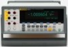
Table 3-2. Display Elements 3 Front-Panel Operation Controls and Indicators 12 11 10 9 8 Item A B C D E F G H I J K L mV V ... 1 100.0002 Hz -0.4561 mV~ 123.123. 123.123. -- 7 ENTER Description 2 3 4 5 6 caw02f.eps Primary display. Secondary display. Indicates PASS, HIGH or LOW for limits testing. Math function selected. Error detected. Memory enabled for storing readings. Extinguishes when last sample is stored. Soft key key labels. Manual range mode selected. See "Adjusting the Meter's Range" section. The Meter is under remote control. External Trigger Enabled. Rear inputs connectors selected. Menu selection path. Measurement results occupy the first two rows of the display. The primary display consists of larger sized characters that comprise the 6½ digits (-1999999 to 1999999), plus a decimal point. In the example shown above, the primary display shows measurement results for an ac voltage measurement. The secondary display is smaller than the primary display and located in the upper right area of the display. However, it is also capable of displaying 6½ digits. Its function is to display the results of a secondary measurement associated with the primary measurement. In the example shown, the secondary display shows the frequency of the ac voltage measurement. The Soft Key labels, row three, identify the functions of the five soft keys just below the display. 3-5
-
 1
1 -
2
-
3
-
4
-
5
-
6
-
7
-
8
-
9
-
10
-
11
-
12
-
13
-
14
-
15
-
16
-
17
-
18
-
19
-
20
-
21
-
22
-
23
-
24
-
25
-
26
-
27
-
28
-
29
-
30
-
31
-
32
-
33
-
34
-
35
-
36
-
37
-
38
-
39
-
 40
40 -
 41
41 -
 42
42 -
 43
43 -
 44
44 -
 45
45 -
 46
46 -
 47
47 -
 48
48 -
 49
49 -
 50
50 -
51
-
52
-
53
-
54
-
55
-
56
-
57
-
58
-
59
-
60
-
61
-
62
-
63
-
64
-
65
-
66
-
67
-
68
-
69
-
70
-
71
-
72
-
73
-
74
-
75
-
76
-
77
-
78
-
79
-
80
-
81
-
82
-
83
-
84
-
85
-
86
-
87
-
88
-
89
-
90
-
91
-
92
-
93
 |
 |
