Fluke 8845A FE 8845A & 8846A Users Manual - Page 76
Testing Continuity, Checking Diodes
 |
View all Fluke 8845A manuals
Add to My Manuals
Save this manual to your list of manuals |
Page 76 highlights
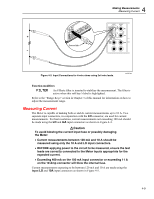
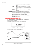
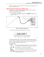
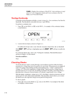
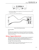
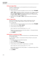
8845A/8846A Users Manual OHMS - Displays the resistance of the RTD. 2-wire resistance is used when in 2-wire temperature mode and 4-wire resistance when the Meter is in 4-wire RTD mode. Testing Continuity Continuity testing determines whether a circuit is intact (i.e., has a resistance less than the threshold). The threshold is selectable between 1 and 1000 Ω. To perform a continuity test: 1. Press S on the 8846A or Q on the 8845A. An example of the continuity display is shown below. OPEN F1 F2 F3 F4 F5 caw12f.eps 2. Connect the test leads as shown in Figure 4-1. If enabled, the beeper emit a tone when the resistance drops below the set threshold. If the BEEP OFF soft key is highlighted, press the BEEP OFF soft key to enable the beeper. To set the threshold value, refer to the "Setting the Continuity Threshold Resistance" section in Chapter 3 of this manual. Function modifiers: None Checking Diodes The diode function sends a current through a semiconductor junction while the Meter measures the voltage drop across the junction (or junctions). Measurements are displayed in the 10 V range at the medium and fast measurement rates. "OPEN" is displayed for voltages 10 % above the compliance voltage setting. Typical junction voltage drop on good junctions are 0.3 to 0.8 volts. If enabled, the beeper will make a short beep when a good junction is detected. Shorted diodes will indicate a significantly lower voltage. With the higher compliance voltage (up to 10 V), the Meter's diode test function can test zeners up to 10 volts, diode stacks and LEDs. The selectable current allows you to tailor the diode test to the expected voltage for the junction being tested. To check a diode: 1. Press S twice on the 8846A or D once on the 8845A. An example of the diode test display is shown below. 4-14
-
 1
1 -
2
-
3
-
4
-
5
-
6
-
7
-
8
-
9
-
10
-
11
-
12
-
13
-
14
-
15
-
16
-
17
-
18
-
19
-
20
-
21
-
22
-
23
-
24
-
25
-
26
-
27
-
28
-
29
-
30
-
31
-
32
-
33
-
34
-
35
-
36
-
37
-
38
-
39
-
40
-
41
-
42
-
43
-
44
-
45
-
46
-
47
-
48
-
49
-
50
-
51
-
52
-
53
-
54
-
55
-
56
-
57
-
58
-
59
-
60
-
61
-
62
-
63
-
64
-
65
-
66
-
67
-
68
-
69
-
70
-
 71
71 -
 72
72 -
 73
73 -
 74
74 -
 75
75 -
 76
76 -
 77
77 -
 78
78 -
 79
79 -
 80
80 -
 81
81 -
82
-
83
-
84
-
85
-
86
-
87
-
88
-
89
-
90
-
91
-
92
-
93
 |
 |
