Fluke 8845A FE 8845A & 8846A Users Manual - Page 43
Introduction, Controls and Indicators, Front-Panel Feature Descriptions - multimeter manual
 |
View all Fluke 8845A manuals
Add to My Manuals
Save this manual to your list of manuals |
Page 43 highlights
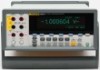
3 Front-Panel Operation Introduction Introduction The Meter can be controlled either by sending commands through one of its communication interfaces or by manual manipulation of its front panel controls. This chapter explains the function and use of the controls and indicators located on the front and rear panels of the Meter. Operating the Meter through its computer interfaces is covered in the Programmers Manual. Controls and Indicators Front-Panel Feature Descriptions Table 3-1 shows the Meter's front-panel controls and connectors. Table 3-1. Front-Panel Controls and Connectors 1 2 3 4 INPUT V 2W/4W HI SENSE 4W HI 1000 V CAT I 600V CAT II 300 V LO LO 1V FUSED 100 mA 10 A REAR FRONT 8846A 6-1/2 DIGIT PRECISION MULTIMETER BACK F1 F2 F3 F4 F5 RANGE DC V AC V DC I FREQ PERIOD AC I TEMP TRIG INSTR SETUP ZERO ANALYZE MEAS SETUP MEMORY 16 15 14 13 12 11 10 8 6 8845A Only FREQ PERIOD 97 5 Item A caw04.eps Description Input HI and LO connectors. Input connectors for Volts, 2-wire Ohms, Hz, Period, Temperature, and Capacitance measurements. All measurements use the Input LO connector as a common input. The LO input is isolated, and may be safely floated up to 1000 V peak above earth ground regardless of the measurement type. 1000 V is the maximum voltage rating between the Input HI and LO connectors. 3-3
-
 1
1 -
2
-
3
-
4
-
5
-
6
-
7
-
8
-
9
-
10
-
11
-
12
-
13
-
14
-
15
-
16
-
17
-
18
-
19
-
20
-
21
-
22
-
23
-
24
-
25
-
26
-
27
-
28
-
29
-
30
-
31
-
32
-
33
-
34
-
35
-
36
-
37
-
 38
38 -
 39
39 -
 40
40 -
 41
41 -
 42
42 -
 43
43 -
 44
44 -
 45
45 -
 46
46 -
 47
47 -
 48
48 -
49
-
50
-
51
-
52
-
53
-
54
-
55
-
56
-
57
-
58
-
59
-
60
-
61
-
62
-
63
-
64
-
65
-
66
-
67
-
68
-
69
-
70
-
71
-
72
-
73
-
74
-
75
-
76
-
77
-
78
-
79
-
80
-
81
-
82
-
83
-
84
-
85
-
86
-
87
-
88
-
89
-
90
-
91
-
92
-
93
 |
 |
