Fluke 8845A FE 8845A & 8846A Users Manual - Page 44
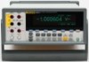
Display Panel, Displays measurements as a value, with measurement units, and measurement statistics
 |
View all Fluke 8845A manuals
Add to My Manuals
Save this manual to your list of manuals |
Page 44 highlights
8845A/8846A Users Manual B Sense HI and LO connectors. Output connectors to source current for 4-wire Ohms measurements. Soft keys F1 through F5. Soft keys are used to select various menu options while C navigating the Meter's menus. Each soft key's function is identified with a label in the bottom row of the display. Keys without a label above them are inactive Memory key for accessing internal and external memory[1] containing meter setups and D measurements. See the "Acessing and Controlling Memory" section for more information. E USB Port. [1] Connection for optional memory device to store meter readings. Standby key to turn off the display. While in standby, the Meter will not respond to F remote or front-panel commands. When taken out of standby, the Meter sets itself to its power-up configuration. G Instrument Setup key. Accesses communications interface selection and setup, remote command set, system settings, and meter reset. Measurement Setup key. Access to resolution setting, trigger functions, temperature H setup, dBm reference selection, continuity settings, and other measurement related parameters. Trigger key. Triggers measurement when trigger is set to external triggering. See the I "Controlling Trigger Functions" section later in this chapter to learn how to use the trigger key (TRIG) to control the Meter's measurement cycle. J Analyze key. Accesses math functions, Statistics, TrendPlot, and Histogram. K Zero key. Uses the present reading as an offset value to create relative readings. Meter function keys. Selects meter function between volts dc, volts ac, amp dc, amps L ac, ohms, continuity, diode test, frequency, period, capacitance [1], and temperature .[1] For the 8845A, the lower four keys change functions; see inset. M Range keys. Selects between manual and auto range mode. Also increases or decreases the range when in manual ranging mode. N Back key. Backs up one layer in the menu selection. O Front and Rear input switch. All front-panel input connectors, except 10 A, is available on the rear-panel of the Meter. These switches switch the Meter's input between them. P 100 mA and 10 A input connectors for ac and dc current measurement functions. Notes: [1] Available on 8846A only Display Panel The display panel described in Table 3-2, performs the following three functions: • Displays measurements as a value, with measurement units, and measurement statistics in both numerical and graphical format (TrendPlot and Histogram). • Displays soft labels for soft keys, F1 through F5. • Identifies the current mode of operation, Local (MAN) or Remote (REM). 3-4
-
 1
1 -
2
-
3
-
4
-
5
-
6
-
7
-
8
-
9
-
10
-
11
-
12
-
13
-
14
-
15
-
16
-
17
-
18
-
19
-
20
-
21
-
22
-
23
-
24
-
25
-
26
-
27
-
28
-
29
-
30
-
31
-
32
-
33
-
34
-
35
-
36
-
37
-
38
-
 39
39 -
 40
40 -
 41
41 -
 42
42 -
 43
43 -
 44
44 -
 45
45 -
 46
46 -
 47
47 -
 48
48 -
 49
49 -
50
-
51
-
52
-
53
-
54
-
55
-
56
-
57
-
58
-
59
-
60
-
61
-
62
-
63
-
64
-
65
-
66
-
67
-
68
-
69
-
70
-
71
-
72
-
73
-
74
-
75
-
76
-
77
-
78
-
79
-
80
-
81
-
82
-
83
-
84
-
85
-
86
-
87
-
88
-
89
-
90
-
91
-
92
-
93
 |
 |
