Foxconn A7GM-S English Manual. - Page 21
Front Panel Connector : FP1, Serial ATA Connectors : SATA_1/2/3/4/5/6, COM Connector : COM1, IrDA
 |
View all Foxconn A7GM-S manuals
Add to My Manuals
Save this manual to your list of manuals |
Page 21 highlights
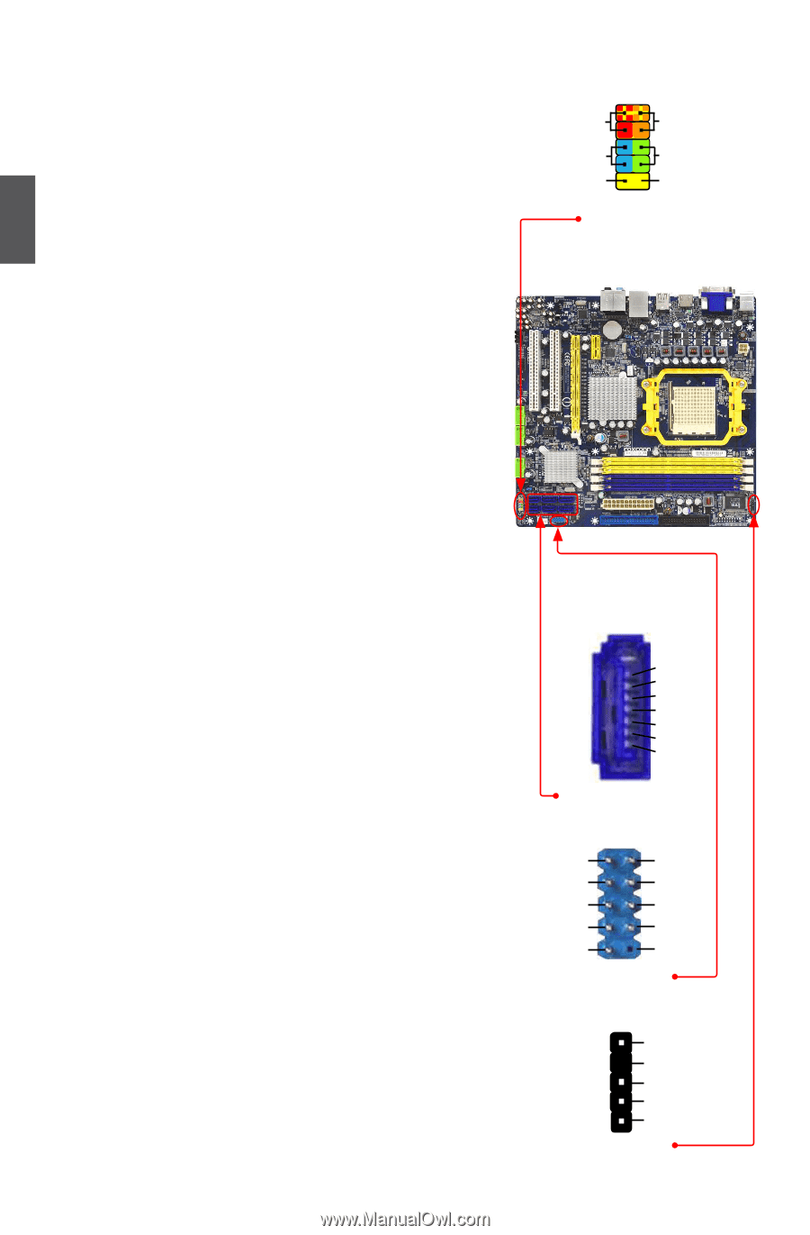
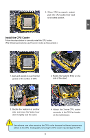
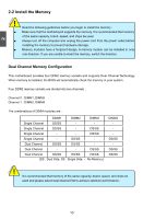
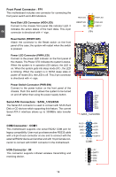
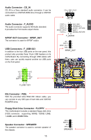
2 Front Panel Connector : FP1 This motherboard includes one connector for connecting the front panel switch and LED Indicators. Hard Disk LED Connector (HDD-LED) Connect to the chassis front panel IDE indicator LED. It indicates the active status of the hard disks. This 2-pin connector is directional with +/- sign. Reset Switch (RESET-SW) Attach the connector to the Reset switch on the front panel of the case; the system will restart when the switch is pressed. Power LED Connector (PWR-LED) Connect to the power LED indicator on the front panel of the chassis. The Power LED indicates the system's status. When the system is in operation (S0 status), the LED is on. When the system gets into sleep mode (S1) , the LED is blinking; When the system is in S3/S4 sleep state or power off mode (S5), the LED is off. This 2-pin connector is directional with +/- sign. Power Switch Connector (PWR-SW) Connect to the power button on the front panel of the chassis. Push this switch allows the system to be turned on and off rather than using the power supply button. Serial ATA Connectors : SATA_1/2/3/4/5/6 The Serial ATA connector is used to connect with SATA Hard Disk or CD devices which supporting this feature. The current Serial ATA II interface allows up to 300MB/s data transfer rate. COM Connector : COM1 This motherboard supports one serial RS232 COM port for legacy compatibility. User must purchase another RS232 cable with a 9-pin D-sub connector at one end to connect with the external RS232 device and another end with 10-pin female connector to connect with COM1 connector in the motherboard. 1 + HDD-LED - 2 + PWR-LED - RESET-SW PWR-SW NC EMPTY 9 10 FP1 1 GND TX+ TX- GND RXRX+ GND SATA_1/2/3/4/5/6 12 RLSD SIN SOUT DTR GND DSR RTS CTS RI EMPTY 9 10 COM1 IrDA Connector : IR This connector supports infrared wireless transmitting and receiving device. 1 2 3 4 5 IR +5V EMPTY IRRX GND IRTX 14
-
 1
1 -
2
-
3
-
4
-
5
-
6
-
7
-
8
-
9
-
10
-
11
-
12
-
13
-
14
-
15
-
 16
16 -
 17
17 -
 18
18 -
 19
19 -
 20
20 -
 21
21 -
 22
22 -
 23
23 -
 24
24 -
 25
25 -
 26
26 -
27
-
28
-
29
-
30
-
31
-
32
-
33
-
34
-
35
-
36
-
37
-
38
-
39
-
40
-
41
-
42
-
43
-
44
-
45
-
46
-
47
-
48
-
49
-
50
-
51
-
52
-
53
-
54
-
55
-
56
-
57
-
58
-
59
-
60
-
61
-
62
-
63
-
64
-
65
-
66
-
67
-
68
-
69
-
70
-
71
-
72
-
73
-
74
-
75
-
76
-
77
-
78
-
79
-
80
-
81
-
82
-
83
-
84
-
85
-
86
-
87
-
88
-
89
-
90
-
91
-
92
-
93
-
94
-
95
-
96
-
97
-
98
-
99
-
100
-
101
-
102
-
103
-
104
-
105
-
106
-
107
 |
 |