Gateway EC14 Service Guide
Gateway EC14 Manual
 |
View all Gateway EC14 manuals
Add to My Manuals
Save this manual to your list of manuals |
Gateway EC14 manual content summary:
- Gateway EC14 | Service Guide - Page 1
Gateway EC18/EC14 Service Guide Service guide files and updates are available on the ACER/CSD web; for more information, please refer to http://csd.acer.com.tw PRINTED IN TAIWAN - Gateway EC14 | Service Guide - Page 2
Revision History Please refer to the table below for the updates made on this service guide. Date Chapter Updates II - Gateway EC14 | Service Guide - Page 3
, manual or otherwise, without the prior written permission of Acer Incorporated. Disclaimer The information in this guide is subject to change without notice. Acer Incorporated makes no representations or warranties, either expressed or implied, with respect to the contents hereof and specifically - Gateway EC14 | Service Guide - Page 4
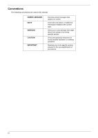
used in this manual: SCREEN MESSAGES NOTE WARNING CAUTION IMPORTANT Denotes actual messages that appear on screen. Gives bits and pieces of additional information related to the current topic. Alerts you to any damage that might result from doing or not doing specific actions. Gives precautionary - Gateway EC14 | Service Guide - Page 5
in the printed Service Guide. For ACER-AUTHORIZED SERVICE PROVIDERS, your Acer office may have a DIFFERENT part number code to those given in the FRU list of this printed Service Guide. You MUST use the list provided by your regional Acer office to order FRU parts for repair and service of customer - Gateway EC14 | Service Guide - Page 6
VI - Gateway EC14 | Service Guide - Page 7
Rear View 8 Indicators 9 TouchPad Basics 10 Using the Keyboard 11 Lock Keys and embedded numeric keypad 11 Windows Keys 12 Hot Keys 13 Special Keys 14 Hardware Specifications and Configurations 15 System Utilities 25 BIOS Setup Utility 25 Navigating the BIOS Utility 25 Information 26 - Gateway EC14 | Service Guide - Page 8
110 Replacing the Keyboard 112 Replacing the Wireless LAN Module 113 Replacing the DIMM Module 115 Replacing the Hard Disk Drive 116 Replacing the Battery 118 Replace the Dummy Card 119 Troubleshooting 121 Common Problems 121 Power On Issue 122 No Display Issue 123 Random Loss of BIOS - Gateway EC14 | Service Guide - Page 9
CMOS Discharge 139 BIOS Recovery by Crisis Disk 140 FRU (Field Replaceable Unit) List 141 Gateway EC18/EC14 Exploded Diagrams 141 Main Assembly 142 LCD Assembly 144 Screw List 150 Model Definition and Configuration 151 Test Compatible Components 155 Online Support Information 159 IX - Gateway EC14 | Service Guide - Page 10
Table of Contents X - Gateway EC14 | Service Guide - Page 11
® processor 723 • Mobile Intel ® US15W Express Chipset System Memory • Dual-channel DDR2 SDRAM support: • Up to 2 GB of DDR2 667 MHz memory, upgradeable to 4 GB using two soDIMM modules (for 32- bit OS) Display and graphics • 11.6" HD 1366 x 768 pixel resolution, high-brightness (200-nit) Gateway - Gateway EC14 | Service Guide - Page 12
battery pack:· • 8-hour battery life9 • Energy Star® • 30W adaptor with power cord Input devices • 84-/85-/88-key full size keyboard, with inverted "T" cursor layou • Touchpad pointing device with two buttons I/O interface • Multi-in-1 card reader • Three USB 2.0 ports • HDMI™ port with HDCP support - Gateway EC14 | Service Guide - Page 13
• Non-operating: 20% to 80% NOTE: The specifications listed above are for reference only. The exact configuration of the PC depends on the model purchased. Chapter 1 3 - Gateway EC14 | Service Guide - Page 14
D 2 C onnector P19 GL AN A ther os A R 8131L SI M CAR D C onnector P19 XTAL Y2 25MHZ I HDA CODE C USB R ealtek A L C 269X XTAL Y3 32.768KHZ PG 11,12,13,14 XTAL P 17 Y4 L PC 32.768KHZ EC W inbond W PC E 775L A 0DG P 18 8x16 K eyboar d C onnector P21 SPI P S /2 FL ASH 2M bytes P 18 - Gateway EC14 | Service Guide - Page 15
and functions of the notebook. LCD View Microphone Webcam Icon Item Webcam Microphone Top View Description Web camera for video communication. Internal microphone for sound recording. Status indicators Keyboard Power button Icon Status indicators Touchpad Item HDD Description Indicates - Gateway EC14 | Service Guide - Page 16
Icon Item Keyboard Touchpad Power Description For entering data into your computer Touch-sensitive pointing device which functions like a computer mouse. Indicates the computer's power status. Battery Bluetooth Communication indicator Click buttons (left, and right) Palmrest Power button/ - Gateway EC14 | Service Guide - Page 17
Multi-in-one card reader Headphones/ speaker/line-out jack with S/PDIF support. Microphone-in jack USB 2.0 port Kensington lock slot Ethernet RJ-45) port Description Accepts Secure Digital (SD), MultiMediaCard(MMC), Memory Stick(MS), Memory Stick PRO (MS PRO), xD-Picture Card (xD). Note: Push to - Gateway EC14 | Service Guide - Page 18
View Battery Battery lock Hard drive bay Battery latch Ventilatio slots and cooling fa Memory bay Wireless module bay Icon Item Battery bay Battery lock Hard disk bay Memory compartment Ventilation slots and cooling fan Battery release latch Rear View Description Houses the computer's battery - Gateway EC14 | Service Guide - Page 19
the computer is on or off. Battery Bluetooth Wireless LAN Indicates the computer's battery status. Indicates the status of Bluetooth communication. Indicates the status of Wireless LAN communication. HDD Num Lock Caps Lock Indicates when the hard disk drive is active. Lights up when Num - Gateway EC14 | Service Guide - Page 20
on the second tap and drag the cursor. NOTE: When using the TouchPad, keep it - and your fingers - dry and clean. The TouchPad is sensitive to finger movement; hence, the lighter the touch, the better the response. Tapping too hard will not increase the TouchPad's responsiveness. 10 Chapter 1 - Gateway EC14 | Service Guide - Page 21
Lock Keys and embedded numeric keypad The keyboard has three lock keys which you can . When Scroll Lock is on, the screen moves one line up or down when you keycaps. To simplify the keyboard legend, cursor-control key -control keys on embedded keypad Main keyboard keys Num Lock on Type numbers - Gateway EC14 | Service Guide - Page 22
Keys The keyboard has two keys that perform Windows-specific functions. Key Description Windows key Pressed alone, this key has the same effect as clicking on the Windows Start button; it launches the Start menu. It can also be used with other keys to provide a variety of functions: < >: Open - Gateway EC14 | Service Guide - Page 23
+ + + + + < > + < > + < > + < > Icon Function System Properties Bluetooth communication switch Sleep Display toggle Screen blank Speaker toggle Brightness up Brightness down Volume up Volume down Description Display the System Properties - Gateway EC14 | Service Guide - Page 24
sign at the upper-center and/or bottom-right of your keyboard. The Euro symbol 1. Open a text editor or word processor. 2. Hold and then press the key at the upper-center of the keyboard. NOTE: Some fonts and software do not support the Euro symbol. See www.microsoft.com/typography/faq - Gateway EC14 | Service Guide - Page 25
Hardware Specifications and Configurations Processor Item CPU type CPU package Chipset Features Specification Intel Penryn SFF (ULV) Micro-FCBGA 956 balls • Intel Crestline GS45 SFF and ICH9M SFF • Supports Intel architecture with Dynamic execution. • On-die, primary 32-kB instruction cache and 32 - Gateway EC14 | Service Guide - Page 26
Technology. • Low Pin Count (LPC) interface. • 6 PCle ports. System Memory Item Memory size DIMM socket number Supports memory size per socket Supports maximum memory size Supports DIMM type Supports DIMM Speed Specification 0MB (No on-board Memory) 2 sockets 2GB 4GB for 64bit OS (with two 2GB SO - Gateway EC14 | Service Guide - Page 27
Features Item Hard Disk Drive Interface Specification • Microsoft Windows Vista* Premium support with the highest level of Windows Aero* experience • Blu-ray* logo capable HD video playback, with native support for Blu-ray* drives • Great 3D graphics performance • Intel® Clear Video Technology - Gateway EC14 | Service Guide - Page 28
Voltage Item Vendor & Model Name Toshiba MK1655GSX Capacity (GB) 160 Bytes per sector 512 Data heads 2 Drive Format Disks 1 Spindle speed (RPM) Performance Specifications Buffer size Interface Internal transfer rate (Mbits/sec, max) I/O data transfer rate (Mbytes/sec max) DC - Gateway EC14 | Service Guide - Page 29
5400 8 MB SATA N/A 300 5V ±5% Specification Insyde 3.5 • Flash ROM 1MB • Support ISIPP • Support Acer UI • Support multi-boot • Suspend to RAM (S3) / Disk (S4) • Various hot-keys for system control • Support SMBUS 2.0, PCI2.3 • ACPI 2.0 compliance with Intel Speed Step Support C1e, C2, C3 and S3 - Gateway EC14 | Service Guide - Page 30
Bluetooth v2.1 with Class 2 specification RF output power. • Enhanced Data Rate (EDR) compliant. • Full Piconet and Scatternet operation. • Integrated PIFA Antenna with better RF performance. • USB 2.0 compliant interface. • F/W upgradable via Flash downloads. • Very low power consumption. • Support - Gateway EC14 | Service Guide - Page 31
decoder, and timing recovery functions to deliver robust signal performance in noisy environments. • The AR8131L GbE controller supports checksum offload features for IP, TCP, and UDP, Specification ACER NT1T JM11 Black 86/87/91 Yes Yes • Supports application keys for Windows XP version Media Card - Gateway EC14 | Service Guide - Page 32
2412 ~ 2484MHz ISM band DQPSK, DBPSK and CCK • 1---11 channels for active channels • 12---13 channels for passive channels 11Mbps with fall back rates of 5.5, 2, and 1Mbps CSMA/CA with ACK 18dBm typically Battery Item Vendor & model name Battery Type Specification 6 Cell SANYO UM-2009E Li-Ion 3S2P - Gateway EC14 | Service Guide - Page 33
Item Pack capacity Number of battery cell Package configuration Specification 6 Cell SANYO 6 cell 4400mAh SANYO 6 cell 5600mAh PANASONIC 6 cell 4400mAh PANASONIC 6 cell 5800mAh SAMSUNG 6 cell 4400mAh SAMSUNG 6 cell 5600mAh LGC 6 cell 5600mAh 6 3 cells in series, 2 series in parallel Chapter 1 23 - Gateway EC14 | Service Guide - Page 34
24 Chapter 1 - Gateway EC14 | Service Guide - Page 35
, you may need to run Setup. Please also refer to Chapter 4 Troubleshooting when problem arises. To activate the BIOS Utility, press F2 during POST (when Press to enter Setup message is prompted on the bottom of screen). Press F2 to enter setup. The default parameter of F12 Boot Menu is set - Gateway EC14 | Service Guide - Page 36
on primary IDE master. This field displays the model name of the installed ODD drive. Displays system BIOS version. This field displays the VGA firmware version of the system. This field by the Open Software Foundation (OSF) as part of the Distributed Computing Environment (DCE). 26 Chapter 2 - Gateway EC14 | Service Guide - Page 37
memory size. VGA Memory size=32 MB This will hide POST messages while booting. Enables, disables the system boot from LAN (remote server). Enables, disables Boot Menu during POST. Enables, disables D2D Recovery function. The function allows the user to create a hidden partition on hard disc drive - Gateway EC14 | Service Guide - Page 38
Set Hdd Password Power on password [Disabled] Item Specific Help Install or Change the password and the length below describes the parameters in this screen. Settings in boldface are the user password is set, this password protects the BIOS Setup Utility from unauthorized access. The user can enter - Gateway EC14 | Service Guide - Page 39
careful when typing your password because the characters do not appear on the screen. 3. Press Enter. After setting the password, the computer sets the . 5. When you are done, press F10 to save the changes and exit the BIOS Setup Utility. Removing a Password Follow these steps: 1. Use the ↑ and ↓ - Gateway EC14 | Service Guide - Page 40
can enable the Password on boot parameter. 6. When you are done, press F10 to save the changes and exit the BIOS Setup Utility. If the verification is OK, the screen will display as following. Setup Notice Changes have been saved. [Continue] The password setting is complete after the user presses - Gateway EC14 | Service Guide - Page 41
system. Bootable devices includes the USB diskette drives, the onboard hard disk drive and the DVD drive in the module bay. Information Main Security InsydeH20 Setup Utility Boot Exit Rev. 3.5 Boot priority order: Item Specific Help 1. IDE0 : Hitachi HTS545032B9A300 2. IDE1 : 3. Network Boot - Gateway EC14 | Service Guide - Page 42
Exit The Exit screen allows you to save or discard any changes you made and quit the BIOS Utility. InsydeH20 Setup Utility Information Main Security Boot Exit Rev. 3.5 Exit Saving Changes Exit Discarding Changes Load Setup Defaults Discard Changes Save Changes Item Specific Help Exit System - Gateway EC14 | Service Guide - Page 43
BIOS Flash Utility The BIOS flash memory update is required for the following conditions: • New versions of system programs • New features or options • Restore a BIOS when it becomes corrupted. Chapter 2 33 - Gateway EC14 | Service Guide - Page 44
USB HDD to Update BIOS, move USB HDD to position 1. Information Main Security InsydeH20 Setup Utility Boot Exit Boot priority order: 1. IDE0 : Hitachi HTS545032B9A300 2. IDE1 : 3. Network Boot : Atheros Boot Agent 4. USB HDD 5. USB CDROM : 6. USB FDD : Rev. 3.5 Item Specific - Gateway EC14 | Service Guide - Page 45
WinFlash Utility Perform the following steps to use the WinFlash Utility: 1. Double click the WinFlash executable. 2. Click OK to begin the update. A progress screen displays. 3. When the process is complete, close all programs and applications and reboot the system. Chapter 2 35 - Gateway EC14 | Service Guide - Page 46
key to create an unlock code. Make a note of the result, for example 46548274. 6. Reboot to the hard disk and wait for the error code to reappear. 7. Press Enter to display the Select Item screen. 8. Select Enter Unlock Password and press Enter. 9. Enter the unlock code generated by UnlockHD.EXE. 10 - Gateway EC14 | Service Guide - Page 47
Password three times, System Disabled displays on the screen. See the image below. To reset the BIOS password, run clnpwd.exe as follows: 1. From a DOS prompt, Execute clnpwd.exe 2. Press 1 or 2 to clean the desired password shown on the screen. The onscreen message determines whether the function - Gateway EC14 | Service Guide - Page 48
BIOS. To use Boot Sequence Selector, perform the following steps: 1. Enter into DOS. 2. Execute BS.exe to display the usage screen. the BIOS displays Verifying DMI pool data it is checking the table correlates with the hardware before sending to the operating system (Windows, etc.). To update the - Gateway EC14 | Service Guide - Page 49
Example 1: Read DMI Information from Memory Input: dmitools /r Output: Manufacturer (Type1, Offset04h): Acer Product Name (Type1, Offset05h): Aspire one xxxxx Serial Number (Type1, Offset07h): 01234567890123456789 UUID String (Type1, Offset08h): xxxxxxxx-xxxx- - Gateway EC14 | Service Guide - Page 50
40 Chapter 2 - Gateway EC14 | Service Guide - Page 51
Chapter 3 Machine Disassembly and Replacement This chapter contains step-by-step procedures on how to disassemble the notebook computer for maintenance and troubleshooting. Disassembly Requirements To disassemble the computer, you need the following tools: • Wrist grounding strap and conductive mat - Gateway EC14 | Service Guide - Page 52
Pre-disassembly Instructions Before proceeding with the disassembly procedure, make sure that you do the following: 1. Turn off the power to the system and all peripherals. 2. Unplug the AC adapter and all power and signal cables from the system. 3. Place the system on a flat, stable surface. 42 - Gateway EC14 | Service Guide - Page 53
components. For example, if you want to remove the Mainboard, you must first remove the Keyboard, and LCD Module then disassemble the inside assembly frame in that order. Main Screw List Screw Quantity Acer Part Number M2.0X2.5-I(BNI)(NYLOK) IRON 4 86.SA107.002 M2*3.0 I (BNI,NYLOK)IRON 16 - Gateway EC14 | Service Guide - Page 54
or configuration. Screw List Step Screw Quantity Part No. WAN Module 2*3 1 Disassembly 86.SA107.001 External Modules Disassembly Flowchart Turn off system and peripherals power Disconnect power and signal cables from system Remove Battery Remove Dummy Card Remove Lower Covers Remove - Gateway EC14 | Service Guide - Page 55
Removing the Battery Pack 1. Turn the computer over. 2. Slide the battery lock/unlock latch to the unlock position. 3. Slide and hold the battery release latch to the release position (1), then slide out the battery pack from the main unit (2). 2 1 Chapter 3 45 - Gateway EC14 | Service Guide - Page 56
Removing the Dummy Card 1. Press the dummy card in to allow it to spring out. 2. Pull the dummy card out. 46 Chapter 3 - Gateway EC14 | Service Guide - Page 57
Removing the Hard Disk Drive Module DISCLAIMER: The notebook sample in the following images shows an FFC. The actual model includes an FPC as pictured in the image on the right. 1. See "Removing the Battery Pack" on page 45. 2. Loosen the four captive screws. 3. Lift the HDD cover up and away by the - Gateway EC14 | Service Guide - Page 58
5. Grasp the plastic tab at the top of the HDD and lift to bring the HDD out of its bay. At the same time, hold the HDD with the other hand and lift to remove from the chassis. 6. Unlock the HDD FPC and pull the FPC away. 48 Chapter 3 - Gateway EC14 | Service Guide - Page 59
Removing the DIMM Module 1. See "Removing the Battery Pack" on page 45. 2. Loosen the four captive screws in the memory cover. 3. Lift the memory cover away. 4. Push outwards the memory module clips. Chapter 3 49 - Gateway EC14 | Service Guide - Page 60
5. Pull the memory module out. 50 Chapter 3 - Gateway EC14 | Service Guide - Page 61
Removing the WLAN Module 1. See "Removing the Battery Pack" on page 45.. 2. Loosen the four captive screws in the memory cover. 3. Lift and remove the memory cover. 4. Detach the two cables from the Wireless LAN module. IMPORTANT:Take note of the Main (1. black) and Auxiliary (2. white) connectors. - Gateway EC14 | Service Guide - Page 62
5. Remove the one screw. Ensure the cables are well clear of the module Screw List Step WAN Module Disassembly Screw 2*3 Quantity 1 Screw Type 6. Pull the WLAN module out and away. 52 Chapter 3 - Gateway EC14 | Service Guide - Page 63
used and that the cables are replaced in the same position. NOTE: The product previews seen in the disassembly procedures may not represent the final product color or configuration. Main Unit Disassembly Flowchart Remove External Modules before proceeding Remove Keyboard Remove Upper Cover Remove - Gateway EC14 | Service Guide - Page 64
Upper Cover Remove Button Board Remove LCD Module Remove LED Board Remove I/O Board Remove Mainboard Screw M2*3 M2*5 M2*3 M2*5 M2*3 M2*3 M2*3 Quantity 3 18 2 2 1 1 4 Part No. 86.SA107.001 86.TG607.004 86.W4107.002 86.TG607.004 86.SA107.001 86.SA107.001 86.SA107.001 54 Chapter 3 - Gateway EC14 | Service Guide - Page 65
Removing the Keyboard IMPORTANT: The keyboard is easily warped or damaged during the removal process. Take care not to use excessive force when removing to prevent damage. 1. See "Removing the Battery Pack" on page 45. 2. See "Removing the Hard Disk Drive Module" on page 47. 3. See "Removing the - Gateway EC14 | Service Guide - Page 66
6. Using the plastic pry, lift up the top edge of the keyboard and then lift the keyboard up. 7. Flip the keyboard over. a. Unlock the FCC a b. Pull the keyboard away b 56 Chapter 3 - Gateway EC14 | Service Guide - Page 67
Removing the Upper Cover 1. See "Removing the Keyboard" on page 55. 2. Disconnect the button board FCC from the main board by unlocking the FCC cable and pulling away. 3. Remove the nine screws in the upper cover. Screw List Step Upper Cover Disassembly Size M2*3 M2*5 Quantity 3 (blue call out) 6 - Gateway EC14 | Service Guide - Page 68
4. Turn the computer over and remove the twelve screws in the bottom cover. Screw List Step Upper Cover Disassembly Size M2*5 Quantity 12 Screw Type 5. Turn the computer over and grasp the upper cover under the top edge. Then pull the upper cover up and away from the computer. 58 Chapter 3 - Gateway EC14 | Service Guide - Page 69
Removing the Button Board IMPORTANT: The Touchpad Board cannot be removed individually. To replace the Touchpad, replace the entire Upper Cover. 1. See "Removing the Upper Cover" on page 57. 2. Unlock and remove the touch-pad to mainboard FCC. 3. Unlock and detach the - Gateway EC14 | Service Guide - Page 70
Screw List Step Button board Size M2*3 5. Lift the button board away Quantity 2 Screw Type 6. Peel the touch-pad FCC away from the adhesive. 7. Unlock the touch-pad FCC and pull the cable away. 60 Chapter 3 - Gateway EC14 | Service Guide - Page 71
8. Lift up and pull the button board to main board FCC free. Chapter 3 61 - Gateway EC14 | Service Guide - Page 72
Removing the LCD Module 1. See "Removing the Upper Cover" on page 57. 2. Pull the WLAN cables through and away from the computer. 3. Lift the transparent adhesive tape off the LCD connector. 62 Chapter 3 - Gateway EC14 | Service Guide - Page 73
4. Push out the LCD connector. 5. Remove the two screws of the LCD module hinges. Screw List Step LCD Module Disassembly Screw M2*5 6. Lift the LCD module away. Quantity 2 Screw Type Chapter 3 63 - Gateway EC14 | Service Guide - Page 74
Removing the LED Board 1. See "Removing the Upper Cover" on page 57. 2. Unlock and remove the LCD board FCC. 3. Remove the single screw securing the LED Board to the Lower Cover. Screw List Step LED Board Disassembly Screw 2*3 Quantity 1 Screw Type 64 Chapter 3 - Gateway EC14 | Service Guide - Page 75
4. Lift off the LCD Board. 5. Unlock and remove the LED board FCC from the mainboard. Chapter 3 65 - Gateway EC14 | Service Guide - Page 76
Removing the Bluetooth Module 1. See "Removing the Upper Cover" on page 57. 2. Detach the Bluetooth module cable from the mainboard. 3. LIft the Bluetooth module away from the computer. 4. Detach the Bluetooth module cable from the module. 66 Chapter 3 - Gateway EC14 | Service Guide - Page 77
Removing the I/O Board 1. See "Removing the Upper Cover" on page 57.. 2. Unlock and remove the I/O board FCC from the main board 3. Unlock and remove the I/O board FCC from the I/O board. 4. Remove the one screw from the I/O board. Chapter 3 67 - Gateway EC14 | Service Guide - Page 78
Screw List Step I/O Board Disassembly Screw M2*3 Quantity 1 Screw Type. 5. Lift the board up from the internal edge and then pull away diagonally. 68 Chapter 3 - Gateway EC14 | Service Guide - Page 79
the LCD Module" on page 62. 3. See "Removing the LED Board" on page 64. 4. See "Removing the Bluetooth Module" on page 66. 5. See "Removing the I/O Board" on page 67. 6. Disconnect the speaker cable from the mainboard. 7. Remove the four screws of the main board and the CRT board. Screw List Step - Gateway EC14 | Service Guide - Page 80
8. Lift the main board and the CRT board out together. Lift the internal edge up first then pull out the external connector edge. NOTE: The hand in the photograph holding on to the CRT board. 70 Chapter 3 - Gateway EC14 | Service Guide - Page 81
Removing the CRT Board 1. See "Removing the Mainboard" on page 69. 2. Disconnect the CRT cable from the CRT board. 3. Disconnect the CRT cable from the main board. Chapter 3 71 - Gateway EC14 | Service Guide - Page 82
Board" on page 71. 3. Remove the five captive screws of the thermal module. 4. Lift the thermal module up slightly and then disconnect the thermal module cable from the main board. 5. Lift the thermal module away from the main board. 72 Chapter 3 - Gateway EC14 | Service Guide - Page 83
Removing the RTC Battery IMPORTANT:Observe local regulations in the disposal of all batteries. 1. See "Removing the Mainboard" on page 69. 2. Pry the RTC battery out of the holding clips. Chapter 3 73 - Gateway EC14 | Service Guide - Page 84
Removing the Speaker Modules 1. See "Removing the Mainboard" on page 69. 2. Remove the tape from the speaker cable. 3. Lift the modules away. NOTE: The modules have adhesive on the base and may require force to free. 74 Chapter 3 - Gateway EC14 | Service Guide - Page 85
and replacement of components, ensure all available cable channels and clips are used and that the cables are replaced in Microphone Remove LCD Brackets Remove LCD Panel Remove LCD FPC Cable Remove Antennas Screw List Step Remove LCD Brackets Remove LCD Panel Screw 2*2.5 2*3 Quantity 4 4 Part - Gateway EC14 | Service Guide - Page 86
Removing the LCD Bezel 1. See "Removing the LCD Module" on page 62. 2. Pry the bezel away from the top and then work down one side, along the bottom, then up the other side. 3. Roll the bezel up and away from the hinges. 76 Chapter 3 - Gateway EC14 | Service Guide - Page 87
Removing the Camera Board 1. See "Removing the LCD Bezel" on page 76. 2. Disconnect the camera connector. 3. Pull up the camera board. Chapter 3 77 - Gateway EC14 | Service Guide - Page 88
Removing the LCD Panel 1. See "Removing the Camera Board" on page 77. 2. Pull up the microphone. 3. Remove the four screws. Screw List Step LCD Panel Disassembly Screw 2x3 Quantity 4 Screw Type 78 Chapter 3 - Gateway EC14 | Service Guide - Page 89
4. Lift the LCD panel out lifting the bottom of the panel first. Chapter 3 79 - Gateway EC14 | Service Guide - Page 90
Removing the LCD Brackets 1. See "Removing the LCD Panel" on page 78. 2. Remove the four LCD bracket screws. Screw List Step LCD Brackets Disassembly Screw M2*2.5 Quantity 4 Screw Type 80 Chapter 3 - Gateway EC14 | Service Guide - Page 91
Removing the FPC Cable 1. See "Removing the LCD Panel" on page 78. 2. Place the panel face down on a clean smooth surface. Pull the microphone/camera cable off the adhesive. 3. Lift up the protective plastic tab. 4. Disconnect the LCD connector. Chapter 3 81 - Gateway EC14 | Service Guide - Page 92
Removing the Antennas 1. See "Removing the LCD Panel" on page 78. 2. Lift up the right antenna pull the cable away from the LCD module. 3. Lift up the left antenna and pull the cable away from the LCD module. 4. Pull up the two adhesive foil tabs from the cables. 82 Chapter 3 - Gateway EC14 | Service Guide - Page 93
5. Remove the antennas completely. Chapter 3 83 - Gateway EC14 | Service Guide - Page 94
Holdtite Adhesives LTD. This is not a specified requirement. The reassembler is free to select an alternative appropriate adhesive. Replacing the Antennas 1. Relay the cables around the module edge for the left antenna. 2. Relay the cables around the module edge for the right antenna. 84 Chapter 3 - Gateway EC14 | Service Guide - Page 95
3. Stick the two antennas down pressing firmly. 4. Stick down the two foil tabs ensuring the screw holes are properly aligned. Chapter 3 85 - Gateway EC14 | Service Guide - Page 96
Replacing the FPC Cable 1. Connect the FPC cable connector. 2. Place the protective clear adhesive tape down firmly over the connector. 3. Apply adhesive behind the cable and stick the FPC cable down on the rear of the panel. 86 Chapter 3 - Gateway EC14 | Service Guide - Page 97
Replacing the LCD Brackets 1. Replace the four screws holding the LCD brackets in place. Screw List Step LCD Brackets Disassembly Screw M2*2.5 Quantity 4 Screw Type Chapter 3 87 - Gateway EC14 | Service Guide - Page 98
the LCD Panel 1. Place the LCD panel into LCD module as shown top edge first, making sure the cable is not trapped behind the panel. 2. Replace the four screws while ensuring the cables pass through the hinges correctly. Screw List Step LCD Panel Assembly Screw 2x3 Quantity 4 Screw Type 88 - Gateway EC14 | Service Guide - Page 99
3. Apply adhesive and stick the microphone down. Chapter 3 89 - Gateway EC14 | Service Guide - Page 100
Replacing the Camera Board 1. Apply adhesive and lay the Camera Board board down pressing firmly. 2. Connect the cable to the Camera Board. 90 Chapter 3 - Gateway EC14 | Service Guide - Page 101
Replacing the LCD Bezel 1. Place the bezel hinge covers over the hinges. 2. Ensure the cables are correctly exiting the hinges. Chapter 3 91 - Gateway EC14 | Service Guide - Page 102
3. Press down around the bezel starting from the bottom and working simultaneously around the edges to the top. 92 Chapter 3 - Gateway EC14 | Service Guide - Page 103
Main Unit Reassembly Process Replacing the Speaker Modules 1. Apply adhesive in two places under the speaker modules. 2. Press down firmly on the two speaker modules. 3. Place tape over the speaker module cables. Chapter 3 93 - Gateway EC14 | Service Guide - Page 104
Replacing the RTC Battery 1. Place the RTC battery into the holding clips on the main board. 94 Chapter 3 - Gateway EC14 | Service Guide - Page 105
Replacing the Thermal Module 1. Connect the thermal module connector to the main board. 2. module in order: 1-2-3. First tighten Screw 1, then screw 2, then screw 3. 3 1 2 IMPORTANT: Incorrect order of screw replacement could harm the CPU. 3. The tighten the other two captive screws Chapter 3 95 - Gateway EC14 | Service Guide - Page 106
Replacing the CRT Board 1. Connect the CRT board cable to the main board. 2. Connect the CRT board cable to the CRT board. 3. Align the CRT board cable carefully between the main board and the CRT board and stick down the attached tape of the cable. 96 Chapter 3 - Gateway EC14 | Service Guide - Page 107
Replacing the Main Board 1. Slide the main board external connector edge in first to the lower case. 2. Replace the four screws to secure the mainboard to the lower cover. Screw List Step Main Board Assembly Screw 2x3 Quantity 4 Screw Type Chapter 3 97 - Gateway EC14 | Service Guide - Page 108
3. Connect the speaker connector. 98 Chapter 3 - Gateway EC14 | Service Guide - Page 109
Replacing the I/O Card 1. Place the I/O card into the lower case edge first. 2. Replace the one screw. Screw List Step I/O Card Assembly Screw 2x3 Quantity 1 Screw Type Chapter 3 99 - Gateway EC14 | Service Guide - Page 110
3. Connect and lock the I/O card FCC to the I/O board. 4. Connect and lock the I/O card FCC to the main board. 100 Chapter 3 - Gateway EC14 | Service Guide - Page 111
Replacing the Bluetooth Module 1. Connect the Bluetooth module cable to the Bluetooth module. 2. Apply adhesive and place the Bluetooth module into place pressing down firmly. 3. Connect the Bluetooth module cable to the main board. Chapter 3 101 - Gateway EC14 | Service Guide - Page 112
Replacing the LED Board 1. Connect and lock the LED board FCC to the mainboard. 2. Place the LED board into place ensuring the slide switches on the front are properly aligned in the lower cover slots. 3. Replace the one screw. 102 Chapter 3 - Gateway EC14 | Service Guide - Page 113
Screw List Step LED Board Assembly Screw M2*3 Quantity 1 Screw Type 4. Connect the LED board FCC to LED board. Chapter 3 103 - Gateway EC14 | Service Guide - Page 114
Replacing the LCD Module 1. Place the LCD module hinges into position on the lower case. 2. Replace the two screws. Screw List Step LCD Module Assembly Screw M2x5 Quantity 2 Screw Type 104 Chapter 3 - Gateway EC14 | Service Guide - Page 115
3. Reconnect the LCD module connector. 4. Press the adhesive plastic tape of the LCD module connector down firmly. Chapter 3 105 - Gateway EC14 | Service Guide - Page 116
5. Relay the WLAN cables around and through the lower case. 106 Chapter 3 - Gateway EC14 | Service Guide - Page 117
Replacing the Button Board 1. Put the button board to main board FCC through the upper cover and lay out correctly. 2. Apply adhesive and stick the touch pad FCC down onto the upper cover. 3. Connect the touch pad FCC to the touch pad. Chapter 3 107 - Gateway EC14 | Service Guide - Page 118
4. Place the button board onto the upper cover and replace the two screws. Screw List Step Button Board Assembly Screw M2*3 Quantity 2 5. Connect and lock the touch pad FCC to the button board. Screw Type 108 Chapter 3 - Gateway EC14 | Service Guide - Page 119
6. Lay the button board FCC down carefully on the upper cover. 7. Connect the button board FCC to the button board. Chapter 3 109 - Gateway EC14 | Service Guide - Page 120
Replacing the Upper Cover 1. Place the upper cover onto the lower cover aligning the hinges first and then press down around the edges. 2. Replace the nine screws. 110 Chapter 3 - Gateway EC14 | Service Guide - Page 121
Screw List Step Upper Cover Assembly Size M2*3 M2*5 Quantity 3 (blue call out) 6 (red call out) Screw Type 3. Turn the computer over and replace the bottom cover twelve screws. Screw List Step Upper Cover Assembly Size M2*5 Quantity 12 Screw Type 4. Turn the computer back over and connect - Gateway EC14 | Service Guide - Page 122
Replacing the Keyboard 1. Connect the FCC to the mainboard. 2. Turn the keyboard over and insert the bottom edge in push down ensure the four latches across the top are fully secured. 112 Chapter 3 - Gateway EC14 | Service Guide - Page 123
Replacing the Wireless LAN Module 1. Place the wireless LAN module into its connector. 2. Replace the one screw. Screw List Step WLAN Assembly Size M2*3 Quantity 1 Screw Type Chapter 3 113 - Gateway EC14 | Service Guide - Page 124
3. Replace the connectors. The white (Aux) cable attaches to the connector marked 2 on the board. The black (Main) cable attaches to the connector marked 1 on the board. 114 Chapter 3 - Gateway EC14 | Service Guide - Page 125
Replacing the DIMM Module 1. Slide the DIMM module into the connector and press down till the locking springs click into place. 2. Place the DIMM module door down edge first. 3. Tighten the four captive screws. Chapter 3 115 - Gateway EC14 | Service Guide - Page 126
Replacing the Hard Disk Drive DISCLAIMER: The notebook sample in the following images shows an FFC. The actual model includes an FPC as the HDD into its bay. 3. Connect the HDD FPC to the main board. NOTE: The cable pictured in the above images may differ from the actual sample. 116 Chapter 3 - Gateway EC14 | Service Guide - Page 127
4. Place the HDD cover in from one edge. 5. Tighten the four captive screws. Chapter 3 117 - Gateway EC14 | Service Guide - Page 128
Replacing the Battery 1. Slide the battery into position. 2. Close the locking latch. 118 Chapter 3 - Gateway EC14 | Service Guide - Page 129
Replace the Dummy Card Push the dummy card into the slot until it clicks into place. Chapter 3 119 - Gateway EC14 | Service Guide - Page 130
120 Chapter 3 - Gateway EC14 | Service Guide - Page 131
Troubleshooting Chapter 4 Common Problems Use the following procedure as a guide for computer problems. NOTE: The diagnostic tests are intended to test 125 Internal Keyboard Failure Page 126 TouchPad Failure Page 127 Internal Speaker Failure Page 128 Internal Microphone Failure Page 129 - Gateway EC14 | Service Guide - Page 132
correct the problem. Do not replace non-defective FRUs: SSttaarrtt OK Check AC/Battery Power on OK Check Daughter/B & FFC Whether OK Swap AC /Battery NG to the problem. 1. Check the power cable is properly connected to the computer and the electrical outlet. 2. Remove any extension cables between - Gateway EC14 | Service Guide - Page 133
doesn't work, perform the following actions one at a time to correct the problem. Do not replace non-defective FRUs: START Replace LCD Panel and No Cable LCD Module OK? Go to No Power Power On ? No troubleshooting step Ext. DDRAM module connected properly? No Reconnect SDRAM Module Ext. DDRAM - Gateway EC14 | Service Guide - Page 134
Information" on page 165. 10. Run the Windows Memory Diagnostic from the operating system DVD and follow the onscreen prompts. 11. If the Issue is still not resolved, see "Online Support Information" on page 165. Random Loss of BIOS Settings If the computer is experiencing intermittent loss of - Gateway EC14 | Service Guide - Page 135
still not resolved, see "Online Support Information" on page 165. LCD Failure If the LCD fails, perform the following actions one at a time to correct the problem. Do not replace nondefective FRUs: Start OK Check LCD module? OK Check MB LCD connector and cable ? Swap NG LCD cable /LCD panel OK - Gateway EC14 | Service Guide - Page 136
Built-In Keyboard Failure If the built-in Keyboard fails, perform the following actions one at a time to correct the problem. Do not replace non-defective FRUs: Start Keyboard properly connected? No Disconnect and reconnect Keyboard functioning? No Replace Keyboard Replace mainboard 126 - Gateway EC14 | Service Guide - Page 137
Failure If the TouchPad doesn't work, perform the following actions one at a time to correct the problem. Do not replace non-defective FRUs: Start OK Check M/B T/P FFC OK Check TouchPad Re-assemble the NG T/P FFC to M/B OK Swap/Reassemble NG the T/P board or T/P FFC Swap M/B Chapter - Gateway EC14 | Service Guide - Page 138
problem. Do not replace non-defective FRUs: Start OK Check M/B SPK cable OK Check Logic Upper/Logic upper Re-assemble the NG SPK cable to Devices. 3. Roll back the audio driver to the previous version, if updated recently. 4. Remove and reinstall the audio driver. 5. Ensure that all volume - Gateway EC14 | Service Guide - Page 139
System. 11. If the Issue is still not resolved, see "Online Support Information" on page 165. Internal Microphone Failure If the internal Microphone fails, perform the following actions one at a time to correct the problem. Do not replace non-defective FRUs: Start OK Check M/B Mic. cable OK Check - Gateway EC14 | Service Guide - Page 140
Run the Windows Memory Diagnostic Tool. For more information see Windows Help and Support. 5. Restart the computer and press F2 to enter the BIOS Utility. Check the BIOS settings are correct and that CD/DVD drive is set as the first boot device on the Boot menu. 6. Ensure all cables and jumpers on - Gateway EC14 | Service Guide - Page 141
USB cable Swap M/B Other Failures If the VGA board, LAN Port, external MIC or Speakers, PCI Express Card, 5-in-1 Card Reader or Volume Wheel fail, perform the following general steps to correct the problem. Do not replace non-defective FRUs: 1. Check whether the drive is OK. 2. Verify that the Test - Gateway EC14 | Service Guide - Page 142
Verify that all attached devices are supported by the computer. NOTE: Verify that problems are found, replace the FRU. 3. Remove or disconnect all of the following devices: • Non-Acer devices • Printer, mouse, and other external devices • Battery pack • Hard disk drive • DIMM • CD-ROM/Diskette drive - Gateway EC14 | Service Guide - Page 143
SecurityStub CpuIo Cf9Reset PcRtc StatusCode Variable SmmVariable EmuVariable Code 01 02 03 04 08 09 0A 0B 0D 0E 12 13 14 15 2F 10 11 31 A4 A5 32 33 34 35 36 8A 37 38 39 3A 3B 3C 3D 3E 3F 40 41 42 CF 43 Chapter 4 133 - Gateway EC14 | Service Guide - Page 144
POST Routine Description TcgDxe PhysicalPresence TpmDriver TcgSmm PhysicalPresenceReadyToBoot DataHubRecordPolicy Undi SNP BC PxeDhcp4 Ebc IsaBus IsaSerial Ps2Mouse IdeBus LightPciBus UsbBot UsbCbi0 UsbCbi1 UsbKb UsbMassStorage UsbMouse Ehci Uhci UsbBus SmmBase SmmDisp SmmReloc SmmRuntime SmmThunk - Gateway EC14 | Service Guide - Page 145
POST Routine Description Fwh SmmFwh PciHotPlug BootOptionPolicy SetupUtility Platform PlatformIde Ppm Platform Ihisi SetupMouse Int15Microcode SmmPnp Smbios MemorySubClass MiscSubclassDriver SysPassword PswdConsole HddPswdServiceBody HddPswdService HiiDatabase OemSetupBrowser Font(English) Font( - Gateway EC14 | Service Guide - Page 146
POST Routine Description AsfInit IdeRController Legacy8259 LegacyRegion LegacyInterrupt BiosKeyboard BiosVideo MonitorKey LegacyBios LegacyBiosPlatform LegacyMouse SmmUsbLegacy AmtbxInvoke OemBadgingSupport Code A7 A9 63 64 65 66 67 68 69 6A 77 78 AA 83 136 Chapter 4 - Gateway EC14 | Service Guide - Page 147
connector SIM card connector Battery connector EC Winbond Codec Card reader board connector Speaker Connector Item CN6 U9 CN2 CN17 CN18 U2 CN4 CN5 Description Bluetooth Connector Clock Generator LED board connector USB connector HDMI HDMI level shift Keyboard connector Touch Pad connector Chapter - Gateway EC14 | Service Guide - Page 148
Mainboard Bottom View BOTTOM SIDE CN10: DDR2 DIMM2 CN12: DDR2 DIMM1 CN9: HDD connector CN15: CRT board connector U18: CPU CN11: Mini Card For WLAN CN13: Mini Card For 3G card U17: NB GS45 CN16: FAN CN14: RTC U19: SB ICH9M Item CN10 CN12 U18 U17 CN16 Description DDR2 DIMM2 DDR2 DIMM1 CPU NB - Gateway EC14 | Service Guide - Page 149
and BIOS Recovery This section provides a procedure for clearing the password and BIOS. The Hardware Open Gap on the main board clears the CMOS of all user settings and restores factory defaults. Mainboard CMOS Discharge Discharging the CMOS clears all user settings. 1. Disassemble the notebook and - Gateway EC14 | Service Guide - Page 150
Steps for BIOS Recovery from USB Storage Before performing this procedure, prepare a Crisis USB key. The Crisis USB key can be made by executing the Crisis Disk program in a functioning system with a Windows XP or Vista OS. IMPORTANT:The Crisis Disk program will overwrite all data on any drive that - Gateway EC14 | Service Guide - Page 151
from those given in the FRU list of this printed Service Guide. You MUST use the local FRU list provided by your regional Acer office to order FRU parts for repair and service of customer machines. NOTE: To scrap or to return the defective parts, you should follow the local government ordinance or - Gateway EC14 | Service Guide - Page 152
Main Assembly Item 1 2 3 4 5 6 7 Description K/B Top Sub Assy Bluetooth Cable Assy FCC LED Cable CRT Board Assy LED Board Assy CRT Cable Assy 142 Part Number KB.I110G.026* 60.WF807.001 50.SA107.001 50.SA107.001 50.SA107.001 55.WF807.001 55.WF807.001 Chapter 6 - Gateway EC14 | Service Guide - Page 153
Item Description Part Number 8 Main Board MB.SA506.001* 9 Thermal Module UMA Assy 10 Base Sub Assy 11 RAM 12 RAM Door Assy 13 Touch Pad Board Assy 14 Bluetooth Module 15 Cardreader Cable FCC 16 Battery 17 LAN Board Assy 18 SD Dummy Card 19 HDD 20 HDD Mylar 60.SA107.006 - Gateway EC14 | Service Guide - Page 154
6 7 Description LCD Bezel LCD Cover LCD Bracket-R LCD Bracket-L LCD Panel Camera LCD Cable w/Microphone Part Number 60.WF807.005 60.WF807.003 33.WF807.002 33.WF807.001 LK.11605.001 57.S6507.002 50.SA107.005 NOTE: Part numbers may be different depending on your model. Please refer to the FRU List - Gateway EC14 | Service Guide - Page 155
Battery SANYO UM-2009E Li-Ion 3S2P SANYO 6 cell 5600mAh Main COMMON ID:UM09E36 Battery SIMPLO UM-2009E Li-Ion 3S2P SAMSUNG 6 cell 5600mAh Main COMMON ID:UM09E70 Battery ) WN6602AH Lan Intel WLAN 512AN_HMWG Shirley Peak 5100 MM#895373 Foxconn Bluetooth FOX BRM 2046 BT2.1 NI.23600.046 NI.23600.047 KI. - Gateway EC14 | Service Guide - Page 156
DANISH 3P PWR CORD V943B30001218008 DANISH 3P POWER CORD AF-S (INDIA) POWER CORD ARGENTINE 3 PIN BLACK POWER CORD JAPANESE POWER CORD BRAZIL IMETRO 3 PIN BLUETOOTH CABLE ACER P/N. 57.S6507.001 57.S6507.002 27.TAXV7.001 27.TATV7.001 27.A50V7.003 27.TATV7.004 27.A03V7.004 27.A99V7.002 - Gateway EC14 | Service Guide - Page 157
UPPER CASE ASSY BLACK W/TP, FFC CABLE *2 UPPER CASE ASSY RED W/TP, FFC CABLE *2 ACER P/N. 60.WF807.001 60.WFA07.001 LOWER CASE ASSY W/SPEAKER FOR 3G LOWER CASE ASSY W/SPEAKER FOR NON 3G 60.WF707.001 60.WF807.002 HDD COVER BLACK 42.WF807.002 RAM COVER BLACK 42.WF807.001 LCD - Gateway EC14 | Service Guide - Page 158
LF F/W:C60F Disk imbalance criteria = 0.014g-cm HDD TOSHIBA 2.5" 5400rpm 320GB MK3255GSX Libra SATA LF F/W:FG011J HDD SEAGATE 2.5" 5400rpm 500GB ST9500325AS Wyatt SATA LF F/W:0001SDM1 HDD WD 2.5" 5400rpm 500GB WD5000BEVT-22ZAT0 ML250 SATA LF F/W:01.01A01 KEYBOARD Keyboard GATEWAY GP1T SJM11 - Gateway EC14 | Service Guide - Page 159
SJM11 87KS Black Portuguese Texture Keyboard GATEWAY GP1T SJM11 86KS Black Russian Texture Keyboard GATEWAY GP1T SJM11 87KS Black SLO/ CRO Texture Keyboard GATEWAY GP1T SJM11 87KS Black Spanish Texture Keyboard GATEWAY GP1T SJM11 87KS Black Sweden Texture Keyboard GATEWAY GP1T SJM11 87KS Black Swiss - Gateway EC14 | Service Guide - Page 160
Heatsink PARTNAME MAINBOARD GS45 ICH9M CPU SU4100B W/O RAM FOR 3G Memory NANYA SO-DIMM DDRII 667 2GB NT2GT64U8HD0BN-3C LF 128*8 0.07um Memory SAMSUNG SO-DIMM DDRII 667 2GB M470T5663QZ3-CE6 LF Memory SAMSUNG SO-DIMM DDRII 667 2GB M470T5663EH3-CE6 LF 128*8 0.055um Memory HYNIX SO-DIMM DDRII 667 2GB - Gateway EC14 | Service Guide - Page 161
EC1801u EC1801m EC1801e EC1802i EC1803i AAP AAP PA PA PA PA AAP AAP Acer Part No LX.WF30Y.005 LX.WF30Y.004 LX.WF30Y.003 LX.WF30Y.002 LX. EM VHP32WTPH1 UMACkk 2G+1G/320/BT/ 6L2.8/5R/CB_n2_0.3D_Gateway 11inch Netbook Bag Black_GEk_EN12 EC1802j VHP32WJP1 UMACkk 2*1G/250/BT/6L2.8/ 5R/CB_n2_0. - Gateway EC14 | Service Guide - Page 162
PA PA PA AAP AAP PA AAP AAP AAP Acer Part No LX.WFA0X.008 LX.WFA0X.005 LX.WFA0X.004 Netbook Bag Black_GEk_EN12 EC1805i EM VHP32WTPH1 UMAGCrr 2*1G/320/BT/ 6L2.8/5R/CB_n2_0.3D_3G_Gateway 11inch Netbook UMA UMA UMA UMA UMA UMA UMA Memory 1 SO2GBII6 SO2GBII6 SO2GBII6 SO2GBII6 SO2GBII6 SO2GBII6 SO2GBII6 - Gateway EC14 | Service Guide - Page 163
VGA Chip UMA UMA UMA UMA UMA UMA UMA UMA Memory 1 SO2GBII6 SO2GBII6 SO2GBII6 SO2GBII6 SO2GBII6 SO1GBII6 SO1GBII6 SO1GBII6 HDD SP1x2HMW SP1x2HMW SP1x2HMW SP1x2HMW SP1x2HMW SP1x2HMW SP1x2HMW SP1x2HMW SP1x2HMW Blue tooth N Battery 6CELL2.2 N 6CELL2.2 N 6CELL2.2 N 6CELL2.2 N 6CELL2.2 - Gateway EC14 | Service Guide - Page 164
Build in SP1x2HMW Wireless LAN1 SP1x2HMW SP1x2HMW SP1x2HMW SP1x2HMW SP1x2HMW SP1x2HMW SP1x2HMW SP1x2HMW SP1x2HMW SP1x2HMW Blue tooth BT 2.1 N N N BT 2.1 BT 2.1 N BT 2.1 BT 2.1 BT 2.1 Battery 6CELL2.8 6CELL2.8 6CELL2.8 6CELL2.8 6CELL2.8 6CELL2.8 6CELL2.8 6CELL2.8 6CELL2.8 6CELL2.8 154 Appendix A - Gateway EC14 | Service Guide - Page 165
-ON Audio Codec Realtek B cover Battery PANASONIC SANYO SANYO SIMPLO SIMPLO SIMPLO SIMPLO Bluetooth Foxconn Type Description Gobi2000 Qualcomm Gobi2000 Black IMR Red IMR Black IMR Red IMR Gateway 11inch Netbook Bag Black Gateway Accessory Gateway 11" Netbook Bag Black 30W 30W 30W Adapter - Gateway EC14 | Service Guide - Page 166
SATA LF F/W:C60F Disk imbalance criteria = 0.014g-cm HDD HGST 2.5" 5400rpm 320GB HTS545032B9A300 Panther B SATA LF F/W:C60F Disk imbalance criteria = 0. 160GB WD1600BEVT-22ZCTO ML160 SATA LF F/W:11.01A11 HDD WD 2.5" 5400rpm 250GB WD2500BEVT-22ZCT0 ML160 SATA LF F/W:11.01A11 HDD WD 2.5" 5400rpm 320GB - Gateway EC14 | Service Guide - Page 167
NANYA SAMSUNG SAMSUNG SAMSUNG SAMSUNG Mouse Gateway NB Chipset INTEL SB Chipset INTEL Software VGA Chip None Type N500GB5.4KS Description HDD WD 2.5" 5400rpm 500GB WD5000BEVT-22ZAT0 ML250 SATA LF F/W:01.01A01 NT1T Keyboard ACER NT-1T JV11 Internal 11 Standard Black NONE Texture AR8131L Atheros - Gateway EC14 | Service Guide - Page 168
BRAND WiFi Antenna WNC Wireless LAN Foxconn INTEL INTEL Liteon Type PIFA 3rd WiFi 1x2 BGN SP1x2HABG SP1x2HMW 3rd WiFi 1x2 BGN Description PIFA Foxconn Wireless LAN Atheros HB93 1x2 BGN (HM) Lan Intel WLAN 512AG_HMWG Shirley Peak 5100 MM#897072 Lan Intel WLAN 512AN_HMWG Shirley Peak 5100 MM#895373 - Gateway EC14 | Service Guide - Page 169
's Notebook, Desktop and Server models including: • Service guides for all models • User's manuals • Training materials • Bios updates • Software utilities • Spare parts lists • TABs (Technical Announcement Bulletin) For these purposes, we have included an Acrobat File to facilitate the problem-free - Gateway EC14 | Service Guide - Page 170
160 - Gateway EC14 | Service Guide - Page 171
19 vendor 19 Version 19 BIOS Utility 25-33 Advanced 28 Boot 31 Exit 32 Navigating 25 Power 31 Save and Exit 32 Security 28 System Security 32 brightness hotkeys 13 Button Board Removing 59 C Camera Board Removing 77, 90 caps lock on indicator 9 Common Problems 122 CRT Cable Removing 69 D DIMM Module - Gateway EC14 | Service Guide - Page 172
33 FRU (Field Replaceable Unit) List 141 H Hard Disk Drive Module Removing 47 Hibernation mode hotkey 13 Hot Keys 11 I Indicators 9 Intermittent Problems 132 Internal Microphone Failure 129 Internal Speaker Failure 128 J Jumper and Connector Locations 137 K Keyboard Removing 55 Keyboard Failure 126 - Gateway EC14 | Service Guide - Page 173
Online Support Information 159 P Panel 5 PC Card 9 Power On Failure 122 S Speaker Module Removing 66 speakers hotkey 13 System Block Diagram 4 T Test Compatible Components 155 Thermal Module Removing 72 Touch Pad Failure 127 Troubleshooting Built-in KB Failure 126 Internal Microphone 129 Internal - Gateway EC14 | Service Guide - Page 174
LCD Failure 125 No Display 123 ODD 131 Other Failures 131 Power On 122 Touch Pad 127 USB 131 U Undetermined Problems 132 Upper Cover Removing 57 USB Failure (Rightside) 131 utility BIOS 25-33 V volume hotkeys 13 W Windows 2000 Environment Test 155 WLAN Board Removing 51 164
-
 1
1 -
 2
2 -
 3
3 -
 4
4 -
 5
5 -
 6
6 -
 7
7 -
8
-
9
-
10
-
11
-
12
-
13
-
14
-
15
-
16
-
17
-
18
-
19
-
20
-
21
-
22
-
23
-
24
-
25
-
26
-
27
-
28
-
29
-
30
-
31
-
32
-
33
-
34
-
35
-
36
-
37
-
38
-
39
-
40
-
41
-
42
-
43
-
44
-
45
-
46
-
47
-
48
-
49
-
50
-
51
-
52
-
53
-
54
-
55
-
56
-
57
-
58
-
59
-
60
-
61
-
62
-
63
-
64
-
65
-
66
-
67
-
68
-
69
-
70
-
71
-
72
-
73
-
74
-
75
-
76
-
77
-
78
-
79
-
80
-
81
-
82
-
83
-
84
-
85
-
86
-
87
-
88
-
89
-
90
-
91
-
92
-
93
-
94
-
95
-
96
-
97
-
98
-
99
-
100
-
101
-
102
-
103
-
104
-
105
-
106
-
107
-
108
-
109
-
110
-
111
-
112
-
113
-
114
-
115
-
116
-
117
-
118
-
119
-
120
-
121
-
122
-
123
-
124
-
125
-
126
-
127
-
128
-
129
-
130
-
131
-
132
-
133
-
134
-
135
-
136
-
137
-
138
-
139
-
140
-
141
-
142
-
143
-
144
-
145
-
146
-
147
-
148
-
149
-
150
-
151
-
152
-
153
-
154
-
155
-
156
-
157
-
158
-
159
-
160
-
161
-
162
-
163
-
164
-
165
-
166
-
167
-
168
-
169
-
170
-
171
-
172
-
173
-
174
 |
 |
Gateway EC18/EC14
Service Guide
PRINTED IN TAIWAN
Service guide files and updates are available
on the ACER/CSD web; for more information,
please refer to