Gateway GT5014H 8511124 - Gateway Canada mBTX Hardware Reference Guide - Page 30
locked position., absence of a pin hole in the processor socket, then return the lever to its
 |
View all Gateway GT5014H manuals
Add to My Manuals
Save this manual to your list of manuals |
Page 30 highlights
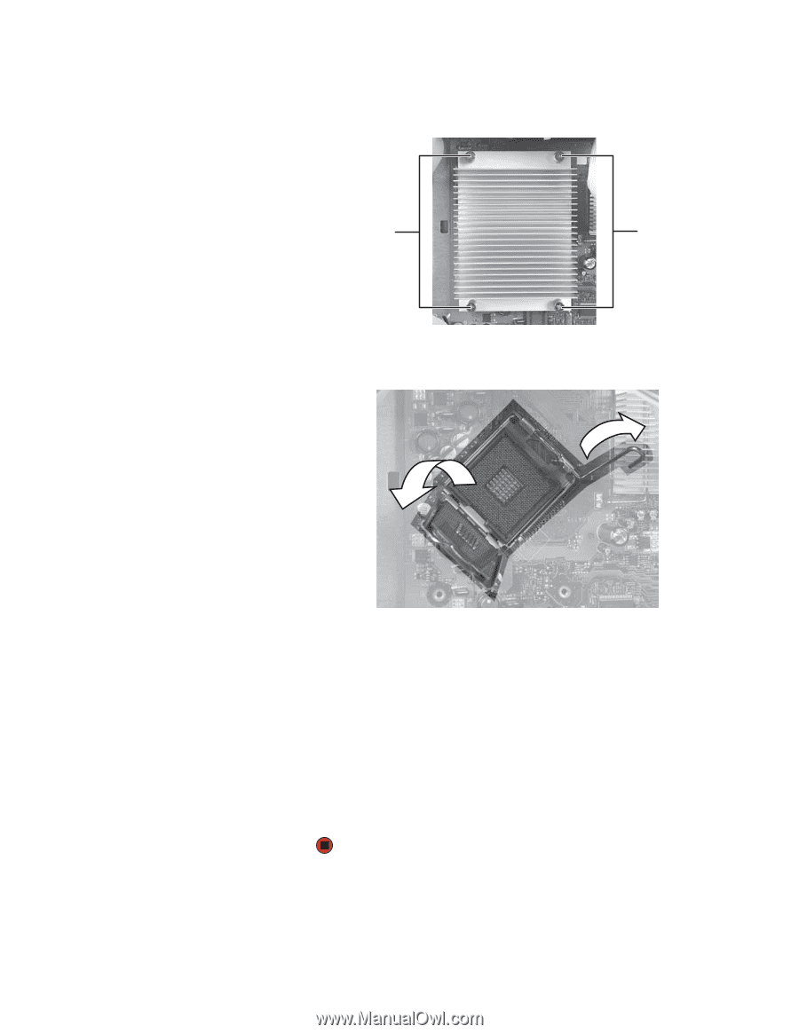
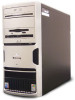
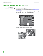
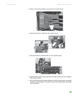
www.gateway.com Replacing the heat sink and processor 5 Loosen the four screws that secure the heat sink to the system board, then remove the heat sink. Screws Screws 6 Release the processor by pushing down on the lever and then lifting it completely up. 7 Remove the processor from the system board. 8 Install the new processor onto the system board making sure that Pin 1 on the processor (indicated by the silk-screened arrow on the corner of the processor) aligns with Pin 1 on the processor socket (indicated by the absence of a pin hole in the processor socket), then return the lever to its locked position. 9 Place the heat sink on the system board, then tighten the screws that secure it to the system board. 10 Connect the fan cable to the system board, then insert the fan into place. 11 Replace the side panel by following the instructions in "Replacing the side panel" on page 14. 27
-
 1
1 -
2
-
3
-
4
-
5
-
6
-
7
-
8
-
9
-
10
-
11
-
12
-
13
-
14
-
15
-
16
-
17
-
18
-
19
-
20
-
21
-
22
-
23
-
24
-
 25
25 -
 26
26 -
 27
27 -
 28
28 -
 29
29 -
 30
30 -
 31
31 -
 32
32 -
 33
33 -
 34
34 -
 35
35 -
36
-
37
-
38
-
39
-
40
-
41
-
42
-
43
-
44
-
45
-
46
-
47
-
48
-
49
-
50
-
51
-
52
-
53
-
54
-
55
-
56
-
57
-
58
-
59
-
60
-
61
-
62
-
63
-
64
-
65
-
66
-
67
-
68
-
69
-
70
-
71
-
72
-
73
-
74
-
75
-
76
-
77
-
78
 |
 |