Gateway GT5014H 8511124 - Gateway Canada mBTX Hardware Reference Guide - Page 35
Step 16, it into the case with the screws.
 |
View all Gateway GT5014H manuals
Add to My Manuals
Save this manual to your list of manuals |
Page 35 highlights
CHAPTER 3: Maintenance Basics www.gateway.com 10 Remove the three screws that secure the power supply to your computer. Screws 11 Slide the power supply away from the back of your computer, then pull it down and remove it. 12 Remove the seven system board screws. Screws Screws 13 Lift the system board up and out of the case. 14 Align the new system board on the screw holes in the case, then secure it into the case with the screws. 15 If your replacement system board does not include a processor, go to Step 16. -ORIf your replacement system board includes a processor, go to Step 20. 32
-
 1
1 -
2
-
3
-
4
-
5
-
6
-
7
-
8
-
9
-
10
-
11
-
12
-
13
-
14
-
15
-
16
-
17
-
18
-
19
-
20
-
21
-
22
-
23
-
24
-
25
-
26
-
27
-
28
-
29
-
 30
30 -
 31
31 -
 32
32 -
 33
33 -
 34
34 -
 35
35 -
 36
36 -
 37
37 -
 38
38 -
 39
39 -
 40
40 -
41
-
42
-
43
-
44
-
45
-
46
-
47
-
48
-
49
-
50
-
51
-
52
-
53
-
54
-
55
-
56
-
57
-
58
-
59
-
60
-
61
-
62
-
63
-
64
-
65
-
66
-
67
-
68
-
69
-
70
-
71
-
72
-
73
-
74
-
75
-
76
-
77
-
78
 |
 |

CHAPTER 3: Maintenance Basics
www.gateway.com
32
10
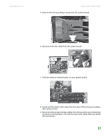
Remove the three screws that secure the power supply to your computer.
11
Slide the power supply away from the back of your computer, then pull
it down and remove it.
12
Remove the seven system board screws.
13
Lift the system board up and out of the case.
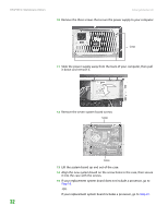
14
Align the new system board on the screw holes in the case, then secure
it into the case with the screws.
15
If your replacement system board does not include a processor, go to
Step 16
.
-OR-
If your replacement system board includes a processor, go to
Step 20
.
Screws
Screws
Screws