HP 6125G HP 6125G & 6125G/XG Blade Switches IP Multicast Configuration - Page 168
Inter-domain multicast delivery through MSDP
 |
View all HP 6125G manuals
Add to My Manuals
Save this manual to your list of manuals |
Page 168 highlights
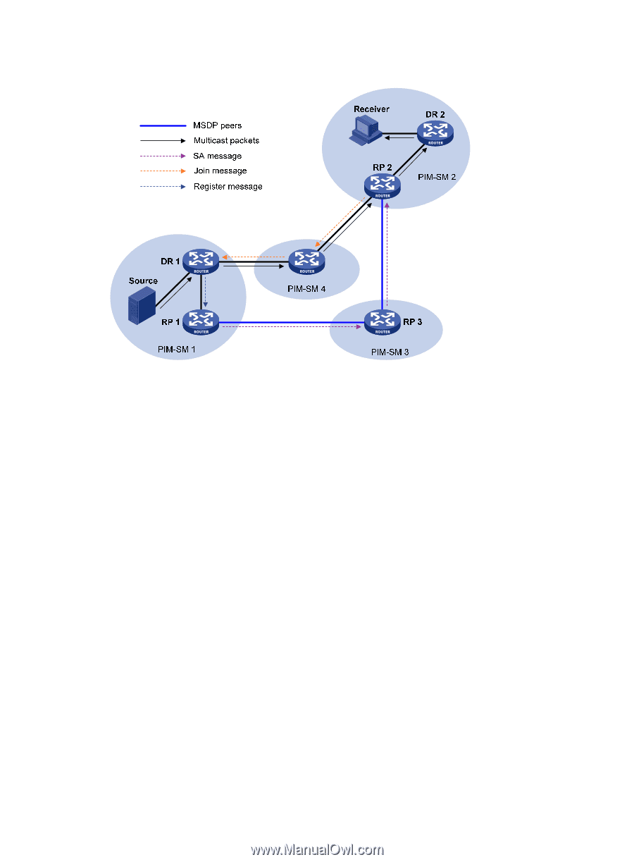
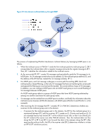
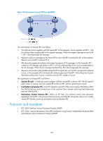
Figure 51 Inter-domain multicast delivery through MSDP The process of implementing PIM-SM inter-domain multicast delivery by leveraging MSDP peers is as follows: 1. When the multicast source in PIM-SM 1 sends the first multicast packet to multicast group G, DR 1 encapsulates the multicast data within a register message and sends the register message to RP 1. Then, RP 1 identifies the information related to the multicast source. 2. As the source-side RP, RP 1 creates SA messages and periodically sends the SA messages to its MSDP peer. An SA message contains the source address (S), the multicast group address (G), and the address of the RP that has created this SA message (namely, RP 1). 3. On MSDP peers, each SA message undergoes a reverse path forwarding (RPF) check and multicast policy-based filtering, so that only SA messages that have arrived along the correct path and passed the filtering are received and forwarded. This avoids delivery loops of SA messages. In addition, you can configure MSDP peers into an MSDP mesh group so as to avoid flooding of SA messages between MSDP peers. An MSDP mesh group refers to a group of MSDP peers that have MSDP peering relationship among one another and share the same group name. 4. SA messages are forwarded from one MSDP peer to another, and finally the information about the multicast source traverses all PIM-SM domains with MSDP peers (PIM-SM 2 and PIM-SM 3, in this example). 5. After receiving the SA message that RP 1 created, RP 2 in PIM-SM 2 determines whether any receivers for the multicast group exist in the domain. { If receivers for the multicast group exist in the domain, the RPT for the multicast group G is maintained between RP 2 and the receivers. RP 2 creates an (S, G) entry and sends an (S, G) join message hop by hop toward DR 1 at the multicast source side, so that it can directly join the SPT rooted at the source over other PIM-SM domains. Then, the multicast data can flow along the SPT to RP 2 and RP 2 can forward the data to the receivers along the RPT. After receiving the multicast traffic, the DR at the receiver side (DR 2) determines whether to initiate an RPT-to-SPT switchover process. 157
-
 1
1 -
2
-
3
-
4
-
5
-
6
-
7
-
8
-
9
-
10
-
11
-
12
-
13
-
14
-
15
-
16
-
17
-
18
-
19
-
20
-
21
-
22
-
23
-
24
-
25
-
26
-
27
-
28
-
29
-
30
-
31
-
32
-
33
-
34
-
35
-
36
-
37
-
38
-
39
-
40
-
41
-
42
-
43
-
44
-
45
-
46
-
47
-
48
-
49
-
50
-
51
-
52
-
53
-
54
-
55
-
56
-
57
-
58
-
59
-
60
-
61
-
62
-
63
-
64
-
65
-
66
-
67
-
68
-
69
-
70
-
71
-
72
-
73
-
74
-
75
-
76
-
77
-
78
-
79
-
80
-
81
-
82
-
83
-
84
-
85
-
86
-
87
-
88
-
89
-
90
-
91
-
92
-
93
-
94
-
95
-
96
-
97
-
98
-
99
-
100
-
101
-
102
-
103
-
104
-
105
-
106
-
107
-
108
-
109
-
110
-
111
-
112
-
113
-
114
-
115
-
116
-
117
-
118
-
119
-
120
-
121
-
122
-
123
-
124
-
125
-
126
-
127
-
128
-
129
-
130
-
131
-
132
-
133
-
134
-
135
-
136
-
137
-
138
-
139
-
140
-
141
-
142
-
143
-
144
-
145
-
146
-
147
-
148
-
149
-
150
-
151
-
152
-
153
-
154
-
155
-
156
-
157
-
158
-
159
-
160
-
161
-
162
-
 163
163 -
 164
164 -
 165
165 -
 166
166 -
 167
167 -
 168
168 -
 169
169 -
 170
170 -
 171
171 -
 172
172 -
 173
173 -
174
-
175
-
176
-
177
-
178
-
179
-
180
-
181
-
182
-
183
-
184
-
185
-
186
-
187
-
188
-
189
-
190
-
191
-
192
-
193
-
194
-
195
-
196
-
197
-
198
-
199
-
200
-
201
-
202
-
203
-
204
-
205
-
206
-
207
-
208
-
209
-
210
-
211
-
212
-
213
-
214
-
215
-
216
-
217
-
218
-
219
-
220
-
221
-
222
-
223
-
224
-
225
-
226
-
227
-
228
-
229
-
230
-
231
-
232
-
233
-
234
-
235
-
236
-
237
-
238
-
239
-
240
-
241
-
242
-
243
-
244
-
245
-
246
-
247
-
248
-
249
-
250
-
251
-
252
-
253
-
254
-
255
-
256
-
257
-
258
-
259
-
260
-
261
-
262
-
263
-
264
-
265
-
266
-
267
-
268
-
269
-
270
-
271
-
272
-
273
-
274
-
275
-
276
-
277
-
278
-
279
-
280
-
281
-
282
-
283
-
284
-
285
-
286
-
287
-
288
-
289
-
290
-
291
-
292
-
293
-
294
-
295
-
296
-
297
-
298
-
299
-
300
-
301
-
302
-
303
-
304
-
305
-
306
-
307
-
308
-
309
-
310
-
311
-
312
-
313
-
314
-
315
-
316
-
317
-
318
-
319
-
320
-
321
-
322
-
323
-
324
-
325
-
326
-
327
-
328
-
329
-
330
-
331
-
332
-
333
-
334
-
335
-
336
-
337
-
338
-
339
-
340
-
341
-
342
-
343
-
344
-
345
-
346
-
347
-
348
-
349
-
350
-
351
-
352
-
353
-
354
-
355
-
356
-
357
-
358
-
359
-
360
-
361
-
362
-
363
-
364
-
365
-
366
-
367
-
368
-
369
-
370
-
371
-
372
-
373
-
374
-
375
-
376
-
377
-
378
-
379
 |
 |