HP 6125G HP 6125G & 6125G/XG Blade Switches IP Multicast Configuration - Page 304
Embedded RP, RPT establishment
 |
View all HP 6125G manuals
Add to My Manuals
Save this manual to your list of manuals |
Page 304 highlights
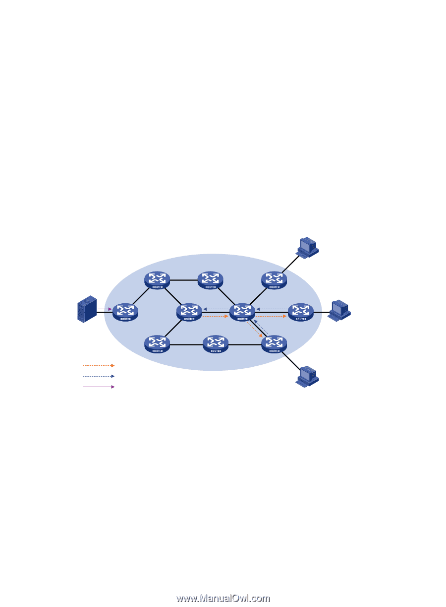
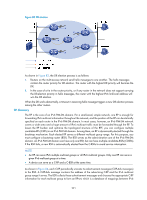
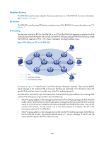
Embedded RP The embedded RP mechanism enables a router to resolve the RP address from an IPv6 multicast address so that the IPv6 multicast group is mapped to an RP. This RP can take the place of the statically configured RP or the RP dynamically calculated based on the BSR mechanism. The DR does not need to identify the RP address beforehand. The specific process is as follows. At the receiver side, the following occur: 1. A receiver host initiates an MLD report to announce that it is joining an IPv6 multicast group. 2. After receiving the MLD report, the receiver-side DR resolves the RP address embedded in the IPv6 multicast address and sends a join message to the RP. At the IPv6 multicast source side, the following occur: 1. The IPv6 multicast source sends IPv6 multicast traffic to the IPv6 multicast group. 2. The source-side DR resolves the RP address embedded in the IPv6 multicast address, and sends a register message to the RP. RPT establishment Figure 85 RPT establishment in an IPv6 PIM-SM domain Source Server Host A Receiver RP DR Host B DR RPT Join message IPv6 multicast packets Receiver Host C As shown in Figure 85, the process of building an RPT is as follows: 1. When a receiver joins IPv6 multicast group G, it uses an MLD report message to inform the directly connected DR. 2. After getting the IPv6 multicast group G's receiver information, the DR sends a join message, which is forwarded hop by hop to the RP that corresponds to the multicast group. 3. The routers along the path from the DR to the RP form an RPT branch. Each router on this branch generates a (*, G) entry in its forwarding table. The asterisk means any IPv6 multicast source. The RP is the root of the RPT, and the DRs are the leaves of the RPT. The IPv6 multicast data addressed to the IPv6 multicast group G flows through the RP, reaches the corresponding DR along the established RPT, and finally is delivered to the receiver. When a receiver is no longer interested in the IPv6 multicast data addressed to a multicast group G, the directly connected DR sends a prune message, which goes hop by hop along the RPT to the RP. After receiving the prune message, the upstream node deletes the interface connected with this downstream 293
-
 1
1 -
2
-
3
-
4
-
5
-
6
-
7
-
8
-
9
-
10
-
11
-
12
-
13
-
14
-
15
-
16
-
17
-
18
-
19
-
20
-
21
-
22
-
23
-
24
-
25
-
26
-
27
-
28
-
29
-
30
-
31
-
32
-
33
-
34
-
35
-
36
-
37
-
38
-
39
-
40
-
41
-
42
-
43
-
44
-
45
-
46
-
47
-
48
-
49
-
50
-
51
-
52
-
53
-
54
-
55
-
56
-
57
-
58
-
59
-
60
-
61
-
62
-
63
-
64
-
65
-
66
-
67
-
68
-
69
-
70
-
71
-
72
-
73
-
74
-
75
-
76
-
77
-
78
-
79
-
80
-
81
-
82
-
83
-
84
-
85
-
86
-
87
-
88
-
89
-
90
-
91
-
92
-
93
-
94
-
95
-
96
-
97
-
98
-
99
-
100
-
101
-
102
-
103
-
104
-
105
-
106
-
107
-
108
-
109
-
110
-
111
-
112
-
113
-
114
-
115
-
116
-
117
-
118
-
119
-
120
-
121
-
122
-
123
-
124
-
125
-
126
-
127
-
128
-
129
-
130
-
131
-
132
-
133
-
134
-
135
-
136
-
137
-
138
-
139
-
140
-
141
-
142
-
143
-
144
-
145
-
146
-
147
-
148
-
149
-
150
-
151
-
152
-
153
-
154
-
155
-
156
-
157
-
158
-
159
-
160
-
161
-
162
-
163
-
164
-
165
-
166
-
167
-
168
-
169
-
170
-
171
-
172
-
173
-
174
-
175
-
176
-
177
-
178
-
179
-
180
-
181
-
182
-
183
-
184
-
185
-
186
-
187
-
188
-
189
-
190
-
191
-
192
-
193
-
194
-
195
-
196
-
197
-
198
-
199
-
200
-
201
-
202
-
203
-
204
-
205
-
206
-
207
-
208
-
209
-
210
-
211
-
212
-
213
-
214
-
215
-
216
-
217
-
218
-
219
-
220
-
221
-
222
-
223
-
224
-
225
-
226
-
227
-
228
-
229
-
230
-
231
-
232
-
233
-
234
-
235
-
236
-
237
-
238
-
239
-
240
-
241
-
242
-
243
-
244
-
245
-
246
-
247
-
248
-
249
-
250
-
251
-
252
-
253
-
254
-
255
-
256
-
257
-
258
-
259
-
260
-
261
-
262
-
263
-
264
-
265
-
266
-
267
-
268
-
269
-
270
-
271
-
272
-
273
-
274
-
275
-
276
-
277
-
278
-
279
-
280
-
281
-
282
-
283
-
284
-
285
-
286
-
287
-
288
-
289
-
290
-
291
-
292
-
293
-
294
-
295
-
296
-
297
-
298
-
 299
299 -
 300
300 -
 301
301 -
 302
302 -
 303
303 -
 304
304 -
 305
305 -
 306
306 -
 307
307 -
 308
308 -
 309
309 -
310
-
311
-
312
-
313
-
314
-
315
-
316
-
317
-
318
-
319
-
320
-
321
-
322
-
323
-
324
-
325
-
326
-
327
-
328
-
329
-
330
-
331
-
332
-
333
-
334
-
335
-
336
-
337
-
338
-
339
-
340
-
341
-
342
-
343
-
344
-
345
-
346
-
347
-
348
-
349
-
350
-
351
-
352
-
353
-
354
-
355
-
356
-
357
-
358
-
359
-
360
-
361
-
362
-
363
-
364
-
365
-
366
-
367
-
368
-
369
-
370
-
371
-
372
-
373
-
374
-
375
-
376
-
377
-
378
-
379
 |
 |