HP 6125G HP 6125G & 6125G/XG Blade Switches IP Multicast Configuration - Page 187
Verifying the configuration, Anycast RP configuration, Network requirements
 |
View all HP 6125G manuals
Add to My Manuals
Save this manual to your list of manuals |
Page 187 highlights
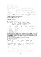
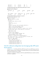
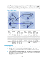
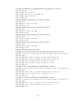
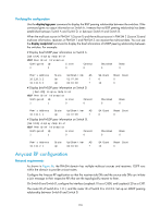
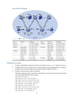
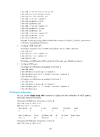
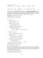
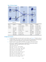
Verifying the configuration Use the display bgp peer command to display the BGP peering relationship between the switches. If the command gives no output information on Switch A, it means that no BGP peering relationship has been established between Switch A and Switch D, or between Switch A and Switch G. When the multicast source in PIM-SM 1 (Source 1) and the multicast source in PIM-SM 2 (Source 2) send multicast information, receivers in PIM-SM 1 and PIM-SM 3 can receive the multicast data. You can use the display msdp brief command to display the brief information of MSDP peering relationship between the switches. For example: # Display brief MSDP peer information on Switch A. [SwitchA] display msdp brief MSDP Peer Brief Information Configured Up Listen Connect 2 2 0 0 Shutdown 0 Down 0 Peer's Address State Up/Down time AS 10.110.3.2 Up 01:07:08 ? 10.110.6.2 Up 00:16:39 ? # Display brief MSDP peer information on Switch D. [SwitchD] display msdp brief MSDP Peer Brief Information Configured Up Listen Connect 1 1 0 0 SA Count 8 13 Reset Count 0 0 Shutdown 0 Down 0 Peer's Address State Up/Down time AS 10.110.1.1 Up 01:07:09 ? # Display brief MSDP peer information on Switch G. [SwitchG] display msdp brief MSDP Peer Brief Information Configured Up Listen Connect 1 1 0 0 SA Count Reset Count 8 0 Shutdown 0 Down 0 Peer's Address State Up/Down time AS 10.110.2.1 Up 00:16:40 ? SA Count Reset Count 13 0 Anycast RP configuration Network requirements As shown in Figure 56, the PIM-SM domain has multiple multicast sources and receivers. OSPF runs within the domain to provide unicast routes. Configure the Anycast RP application so that the receiver-side DRs and the source-side DRs can initiate a join message to their respective RPs that are the topologically nearest to them. On Switch B and Switch D, configure the interface Loopback 10 as a C-BSR, and Loopback 20 as a C-RP. The router ID of Switch B is 1.1.1.1, and the router ID of Switch D is 2.2.2.2. Set up an MSDP peering relationship between Switch B and Switch D. 176
-
 1
1 -
2
-
3
-
4
-
5
-
6
-
7
-
8
-
9
-
10
-
11
-
12
-
13
-
14
-
15
-
16
-
17
-
18
-
19
-
20
-
21
-
22
-
23
-
24
-
25
-
26
-
27
-
28
-
29
-
30
-
31
-
32
-
33
-
34
-
35
-
36
-
37
-
38
-
39
-
40
-
41
-
42
-
43
-
44
-
45
-
46
-
47
-
48
-
49
-
50
-
51
-
52
-
53
-
54
-
55
-
56
-
57
-
58
-
59
-
60
-
61
-
62
-
63
-
64
-
65
-
66
-
67
-
68
-
69
-
70
-
71
-
72
-
73
-
74
-
75
-
76
-
77
-
78
-
79
-
80
-
81
-
82
-
83
-
84
-
85
-
86
-
87
-
88
-
89
-
90
-
91
-
92
-
93
-
94
-
95
-
96
-
97
-
98
-
99
-
100
-
101
-
102
-
103
-
104
-
105
-
106
-
107
-
108
-
109
-
110
-
111
-
112
-
113
-
114
-
115
-
116
-
117
-
118
-
119
-
120
-
121
-
122
-
123
-
124
-
125
-
126
-
127
-
128
-
129
-
130
-
131
-
132
-
133
-
134
-
135
-
136
-
137
-
138
-
139
-
140
-
141
-
142
-
143
-
144
-
145
-
146
-
147
-
148
-
149
-
150
-
151
-
152
-
153
-
154
-
155
-
156
-
157
-
158
-
159
-
160
-
161
-
162
-
163
-
164
-
165
-
166
-
167
-
168
-
169
-
170
-
171
-
172
-
173
-
174
-
175
-
176
-
177
-
178
-
179
-
180
-
181
-
 182
182 -
 183
183 -
 184
184 -
 185
185 -
 186
186 -
 187
187 -
 188
188 -
 189
189 -
 190
190 -
 191
191 -
 192
192 -
193
-
194
-
195
-
196
-
197
-
198
-
199
-
200
-
201
-
202
-
203
-
204
-
205
-
206
-
207
-
208
-
209
-
210
-
211
-
212
-
213
-
214
-
215
-
216
-
217
-
218
-
219
-
220
-
221
-
222
-
223
-
224
-
225
-
226
-
227
-
228
-
229
-
230
-
231
-
232
-
233
-
234
-
235
-
236
-
237
-
238
-
239
-
240
-
241
-
242
-
243
-
244
-
245
-
246
-
247
-
248
-
249
-
250
-
251
-
252
-
253
-
254
-
255
-
256
-
257
-
258
-
259
-
260
-
261
-
262
-
263
-
264
-
265
-
266
-
267
-
268
-
269
-
270
-
271
-
272
-
273
-
274
-
275
-
276
-
277
-
278
-
279
-
280
-
281
-
282
-
283
-
284
-
285
-
286
-
287
-
288
-
289
-
290
-
291
-
292
-
293
-
294
-
295
-
296
-
297
-
298
-
299
-
300
-
301
-
302
-
303
-
304
-
305
-
306
-
307
-
308
-
309
-
310
-
311
-
312
-
313
-
314
-
315
-
316
-
317
-
318
-
319
-
320
-
321
-
322
-
323
-
324
-
325
-
326
-
327
-
328
-
329
-
330
-
331
-
332
-
333
-
334
-
335
-
336
-
337
-
338
-
339
-
340
-
341
-
342
-
343
-
344
-
345
-
346
-
347
-
348
-
349
-
350
-
351
-
352
-
353
-
354
-
355
-
356
-
357
-
358
-
359
-
360
-
361
-
362
-
363
-
364
-
365
-
366
-
367
-
368
-
369
-
370
-
371
-
372
-
373
-
374
-
375
-
376
-
377
-
378
-
379
 |
 |