HP 6125G HP 6125G & 6125G/XG Blade Switches IP Multicast Configuration - Page 339
IPv6 PIM-SM admin-scope zone configuration example, Network requirements, MLDv1 runs between Switch
 |
View all HP 6125G manuals
Add to My Manuals
Save this manual to your list of manuals |
Page 339 highlights
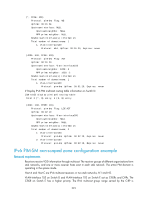
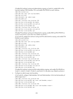
Protocol: pim-sm, Flag: SPT LOC ACT UpTime: 00:14:44 Upstream interface: Vlan-interface300 Upstream neighbor: NULL RPF prime neighbor: NULL Downstream interface(s) information: Total number of downstreams: 1 1: Vlan-interface105 Protocol: mld, UpTime: 00:14:44, Expires: 00:02:26 # Display IPv6 PIM multicast routing table information on Switch E. [SwitchE] display pim ipv6 routing-table Total 1 (*, G) entry; 0 (S, G) entry (*, FF0E::100) RP: 1003::2 (local) Protocol: pim-sm, Flag: WC UpTime: 00:16:56 Upstream interface: Register Upstream neighbor: 4002::1 RPF prime neighbor: 4002::1 Downstream interface(s) information: Total number of downstreams: 1 1: Vlan-interface102 Protocol: pim-sm, UpTime: 00:16:56, Expires: 00:02:34 IPv6 PIM-SM admin-scope zone configuration example Network requirements Receivers receive VOD information through multicast. The entire IPv6 PIM-SM domain is divided into IPv6 admin-scope zone 1, IPv6 admin-scope zone 2, and the IPv6 global zone. Switch B, Switch C, and Switch D are ZBRs of these three domains respectively. Source 1 and Source 2 send different multicast information to FF14::101. Host A receives the multicast information only from Source 1, and Host B receives the multicast information only from Source 2. Source 3 sends multicast information to multicast group FF1E::202. Host C is a multicast receiver for this multicast group. VLAN-interface 101 of Switch B acts as a C-BSR and C-RP of admin-scope zone 1, which serves the IPv6 multicast groups with the Scope field value in their group addresses being 4. VLAN-interface 104 of Switch D acts as a C-BSR and C-RP of admin-scope zone 2, which also serves the IPv6 multicast groups with the Scope field value in their group addresses being 4. VLAN-interface 109 of Switch F acts as C-BSRs and C-RPs of the global scope zone, which serves IPv6 multicast groups with the Scope field value in their group addresses being 14. MLDv1 runs between Switch A, Switch E, Switch I, and their respective receivers. 328
-
 1
1 -
2
-
3
-
4
-
5
-
6
-
7
-
8
-
9
-
10
-
11
-
12
-
13
-
14
-
15
-
16
-
17
-
18
-
19
-
20
-
21
-
22
-
23
-
24
-
25
-
26
-
27
-
28
-
29
-
30
-
31
-
32
-
33
-
34
-
35
-
36
-
37
-
38
-
39
-
40
-
41
-
42
-
43
-
44
-
45
-
46
-
47
-
48
-
49
-
50
-
51
-
52
-
53
-
54
-
55
-
56
-
57
-
58
-
59
-
60
-
61
-
62
-
63
-
64
-
65
-
66
-
67
-
68
-
69
-
70
-
71
-
72
-
73
-
74
-
75
-
76
-
77
-
78
-
79
-
80
-
81
-
82
-
83
-
84
-
85
-
86
-
87
-
88
-
89
-
90
-
91
-
92
-
93
-
94
-
95
-
96
-
97
-
98
-
99
-
100
-
101
-
102
-
103
-
104
-
105
-
106
-
107
-
108
-
109
-
110
-
111
-
112
-
113
-
114
-
115
-
116
-
117
-
118
-
119
-
120
-
121
-
122
-
123
-
124
-
125
-
126
-
127
-
128
-
129
-
130
-
131
-
132
-
133
-
134
-
135
-
136
-
137
-
138
-
139
-
140
-
141
-
142
-
143
-
144
-
145
-
146
-
147
-
148
-
149
-
150
-
151
-
152
-
153
-
154
-
155
-
156
-
157
-
158
-
159
-
160
-
161
-
162
-
163
-
164
-
165
-
166
-
167
-
168
-
169
-
170
-
171
-
172
-
173
-
174
-
175
-
176
-
177
-
178
-
179
-
180
-
181
-
182
-
183
-
184
-
185
-
186
-
187
-
188
-
189
-
190
-
191
-
192
-
193
-
194
-
195
-
196
-
197
-
198
-
199
-
200
-
201
-
202
-
203
-
204
-
205
-
206
-
207
-
208
-
209
-
210
-
211
-
212
-
213
-
214
-
215
-
216
-
217
-
218
-
219
-
220
-
221
-
222
-
223
-
224
-
225
-
226
-
227
-
228
-
229
-
230
-
231
-
232
-
233
-
234
-
235
-
236
-
237
-
238
-
239
-
240
-
241
-
242
-
243
-
244
-
245
-
246
-
247
-
248
-
249
-
250
-
251
-
252
-
253
-
254
-
255
-
256
-
257
-
258
-
259
-
260
-
261
-
262
-
263
-
264
-
265
-
266
-
267
-
268
-
269
-
270
-
271
-
272
-
273
-
274
-
275
-
276
-
277
-
278
-
279
-
280
-
281
-
282
-
283
-
284
-
285
-
286
-
287
-
288
-
289
-
290
-
291
-
292
-
293
-
294
-
295
-
296
-
297
-
298
-
299
-
300
-
301
-
302
-
303
-
304
-
305
-
306
-
307
-
308
-
309
-
310
-
311
-
312
-
313
-
314
-
315
-
316
-
317
-
318
-
319
-
320
-
321
-
322
-
323
-
324
-
325
-
326
-
327
-
328
-
329
-
330
-
331
-
332
-
333
-
 334
334 -
 335
335 -
 336
336 -
 337
337 -
 338
338 -
 339
339 -
 340
340 -
 341
341 -
 342
342 -
 343
343 -
 344
344 -
345
-
346
-
347
-
348
-
349
-
350
-
351
-
352
-
353
-
354
-
355
-
356
-
357
-
358
-
359
-
360
-
361
-
362
-
363
-
364
-
365
-
366
-
367
-
368
-
369
-
370
-
371
-
372
-
373
-
374
-
375
-
376
-
377
-
378
-
379
 |
 |