HP 6125G HP 6125G & 6125G/XG Blade Switches IP Multicast Configuration - Page 180
Switch C, and Switch F in the same way. Details not shown.
 |
View all HP 6125G manuals
Add to My Manuals
Save this manual to your list of manuals |
Page 180 highlights
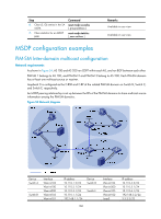
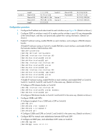
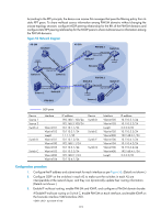
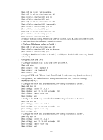
Switch C Loop0 Vlan-int104 Vlan-int102 Vlan-int101 Loop0 1.1.1.1/32 10.110.4.1/24 192.168.3.1/24 192.168.1.2/24 2.2.2.2/32 Switch F Source 1 Source 2 Vlan-int105 Vlan-int400 - - 10.110.6.2/24 10.110.7.1/24 10.110.2.100/24 10.110.5.100/24 Configuration procedure 1. Configure the IP address and subnet mask for each interface as per Figure 54. (Details not shown.) 2. Configure OSPF on switches in each AS to make sure the switches in each AS are interoperable at the network-layer, and they can dynamically update their routing information. (Details not shown.) 3. Enable IP multicast routing, enable PIM-SM on each interface, and configure a PIM-SM domain border: # Enable IP multicast routing on Switch A, enable PIM-SM on each interface, and enable IGMP on the host-side interface VLAN-interface 200. system-view [SwitchA] multicast routing-enable [SwitchA] interface vlan-interface 103 [SwitchA-Vlan-interface103] pim sm [SwitchA-Vlan-interface103] quit [SwitchA] interface vlan-interface 100 [SwitchA-Vlan-interface100] pim sm [SwitchA-Vlan-interface100] quit [SwitchA] interface vlan-interface 200 [SwitchA-Vlan-interface200] igmp enable [SwitchA-Vlan-interface200] pim sm [SwitchA-Vlan-interface200] quit # Enable IP multicast routing, enable PIM-SM on each interface, and enable IGMP on Switch B, Switch C, Switch D, Switch E, and Switch F in the same way. (Details not shown.) # Configure a PIM domain border on Switch B. [SwitchB] interface vlan-interface 101 [SwitchB-Vlan-interface101] pim bsr-boundary [SwitchB-Vlan-interface101] quit # Configure a PIM domain border on Switch C and Switch E in the same way. (Details not shown.) 4. Configure C-BSRs and C-RPs: # Configure Loopback 0 as a C-BSR and a C-RP on Switch B. [SwitchB] pim [SwitchB-pim] c-bsr loopback 0 [SwitchB-pim] c-rp loopback 0 [SwitchB-pim] quit # Configure C-BSRs and C-RPs on Switch C and Switch E in the same way. (Details not shown.) 5. Configure BGP for mutual route redistribution between BGP and OSPF: # Configure an EBGP peer, and redistribute OSPF routes on Switch B. [SwitchB] bgp 100 [SwitchB-bgp] router-id 1.1.1.1 169
-
 1
1 -
2
-
3
-
4
-
5
-
6
-
7
-
8
-
9
-
10
-
11
-
12
-
13
-
14
-
15
-
16
-
17
-
18
-
19
-
20
-
21
-
22
-
23
-
24
-
25
-
26
-
27
-
28
-
29
-
30
-
31
-
32
-
33
-
34
-
35
-
36
-
37
-
38
-
39
-
40
-
41
-
42
-
43
-
44
-
45
-
46
-
47
-
48
-
49
-
50
-
51
-
52
-
53
-
54
-
55
-
56
-
57
-
58
-
59
-
60
-
61
-
62
-
63
-
64
-
65
-
66
-
67
-
68
-
69
-
70
-
71
-
72
-
73
-
74
-
75
-
76
-
77
-
78
-
79
-
80
-
81
-
82
-
83
-
84
-
85
-
86
-
87
-
88
-
89
-
90
-
91
-
92
-
93
-
94
-
95
-
96
-
97
-
98
-
99
-
100
-
101
-
102
-
103
-
104
-
105
-
106
-
107
-
108
-
109
-
110
-
111
-
112
-
113
-
114
-
115
-
116
-
117
-
118
-
119
-
120
-
121
-
122
-
123
-
124
-
125
-
126
-
127
-
128
-
129
-
130
-
131
-
132
-
133
-
134
-
135
-
136
-
137
-
138
-
139
-
140
-
141
-
142
-
143
-
144
-
145
-
146
-
147
-
148
-
149
-
150
-
151
-
152
-
153
-
154
-
155
-
156
-
157
-
158
-
159
-
160
-
161
-
162
-
163
-
164
-
165
-
166
-
167
-
168
-
169
-
170
-
171
-
172
-
173
-
174
-
 175
175 -
 176
176 -
 177
177 -
 178
178 -
 179
179 -
 180
180 -
 181
181 -
 182
182 -
 183
183 -
 184
184 -
 185
185 -
186
-
187
-
188
-
189
-
190
-
191
-
192
-
193
-
194
-
195
-
196
-
197
-
198
-
199
-
200
-
201
-
202
-
203
-
204
-
205
-
206
-
207
-
208
-
209
-
210
-
211
-
212
-
213
-
214
-
215
-
216
-
217
-
218
-
219
-
220
-
221
-
222
-
223
-
224
-
225
-
226
-
227
-
228
-
229
-
230
-
231
-
232
-
233
-
234
-
235
-
236
-
237
-
238
-
239
-
240
-
241
-
242
-
243
-
244
-
245
-
246
-
247
-
248
-
249
-
250
-
251
-
252
-
253
-
254
-
255
-
256
-
257
-
258
-
259
-
260
-
261
-
262
-
263
-
264
-
265
-
266
-
267
-
268
-
269
-
270
-
271
-
272
-
273
-
274
-
275
-
276
-
277
-
278
-
279
-
280
-
281
-
282
-
283
-
284
-
285
-
286
-
287
-
288
-
289
-
290
-
291
-
292
-
293
-
294
-
295
-
296
-
297
-
298
-
299
-
300
-
301
-
302
-
303
-
304
-
305
-
306
-
307
-
308
-
309
-
310
-
311
-
312
-
313
-
314
-
315
-
316
-
317
-
318
-
319
-
320
-
321
-
322
-
323
-
324
-
325
-
326
-
327
-
328
-
329
-
330
-
331
-
332
-
333
-
334
-
335
-
336
-
337
-
338
-
339
-
340
-
341
-
342
-
343
-
344
-
345
-
346
-
347
-
348
-
349
-
350
-
351
-
352
-
353
-
354
-
355
-
356
-
357
-
358
-
359
-
360
-
361
-
362
-
363
-
364
-
365
-
366
-
367
-
368
-
369
-
370
-
371
-
372
-
373
-
374
-
375
-
376
-
377
-
378
-
379
 |
 |