HP 6125G HP 6125G & 6125G/XG Blade Switches IP Multicast Configuration - Page 231
Configuring the source IPv6 addresses for the MLD messages sent by the proxy
 |
View all HP 6125G manuals
Add to My Manuals
Save this manual to your list of manuals |
Page 231 highlights
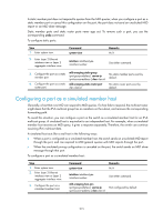
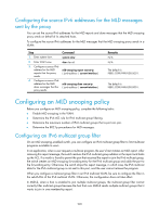
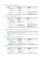
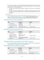
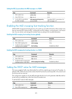
Configuring the source IPv6 addresses for the MLD messages sent by the proxy You can set the source IPv6 addresses for the MLD reports and done messages that the MLD snooping proxy sends on behalf of its attached hosts. To configure the source IPv6 addresses for the MLD messages that the MLD snooping proxy sends in a VLAN: Step 1. Enter system view. 2. Enter VLAN view. 3. Configure a source IPv6 address for the MLD reports that the proxy sends. 4. Configure a source IPv6 address for the MLD done messages that the proxy sends. Command system-view vlan vlan-id mld-snooping report source-ip { ipv6-address | current-interface } mld-snooping done source-ip { ipv6-address | current-interface } Remarks N/A N/A The default is FE80::02FF:FFFF:FE00:0001. The default is FE80::02FF:FFFF:FE00:0001. Configuring an MLD snooping policy Before you configure an MLD snooping policy, complete the following tasks: • Enable MLD snooping in the VLAN. • Determine the IPv6 ACL rule for IPv6 multicast group filtering. • Determine the maximum number of IPv6 multicast groups that a port can join. • Determine the 802.1p precedence for MLD messages. Configuring an IPv6 multicast group filter On an MLD snooping-enabled switch, you can configure an IPv6 multicast group filter to limit multicast programs available to users. In an application, when a user requests a multicast program, the user's host initiates an MLD report. After receiving this report message, the switch resolves the IPv6 multicast group address in the report and looks up the ACL. If a match is found to permit the port that received the report to join the IPv6 multicast group, the switch creates an MLD snooping forwarding entry for the IPv6 multicast group and adds the port to the forwarding entry. Otherwise, the switch drops this report message, in which case, the IPv6 multicast data for the IPv6 multicast group is not sent to this port, and the user cannot retrieve the program. When you configure a multicast group filter in an IPv6 multicast VLAN, be sure to configure the filter in the sub-VLANs of the IPv6 multicast VLAN. Otherwise, the configuration does not take effect. In MLDv2, when a host is enabled to join multiple multicast groups, the multicast group filter cannot correctly filter multicast groups because the host that runs MLDv2 sends multiple multicast groups that it wants to join in one membership report. 220
-
 1
1 -
2
-
3
-
4
-
5
-
6
-
7
-
8
-
9
-
10
-
11
-
12
-
13
-
14
-
15
-
16
-
17
-
18
-
19
-
20
-
21
-
22
-
23
-
24
-
25
-
26
-
27
-
28
-
29
-
30
-
31
-
32
-
33
-
34
-
35
-
36
-
37
-
38
-
39
-
40
-
41
-
42
-
43
-
44
-
45
-
46
-
47
-
48
-
49
-
50
-
51
-
52
-
53
-
54
-
55
-
56
-
57
-
58
-
59
-
60
-
61
-
62
-
63
-
64
-
65
-
66
-
67
-
68
-
69
-
70
-
71
-
72
-
73
-
74
-
75
-
76
-
77
-
78
-
79
-
80
-
81
-
82
-
83
-
84
-
85
-
86
-
87
-
88
-
89
-
90
-
91
-
92
-
93
-
94
-
95
-
96
-
97
-
98
-
99
-
100
-
101
-
102
-
103
-
104
-
105
-
106
-
107
-
108
-
109
-
110
-
111
-
112
-
113
-
114
-
115
-
116
-
117
-
118
-
119
-
120
-
121
-
122
-
123
-
124
-
125
-
126
-
127
-
128
-
129
-
130
-
131
-
132
-
133
-
134
-
135
-
136
-
137
-
138
-
139
-
140
-
141
-
142
-
143
-
144
-
145
-
146
-
147
-
148
-
149
-
150
-
151
-
152
-
153
-
154
-
155
-
156
-
157
-
158
-
159
-
160
-
161
-
162
-
163
-
164
-
165
-
166
-
167
-
168
-
169
-
170
-
171
-
172
-
173
-
174
-
175
-
176
-
177
-
178
-
179
-
180
-
181
-
182
-
183
-
184
-
185
-
186
-
187
-
188
-
189
-
190
-
191
-
192
-
193
-
194
-
195
-
196
-
197
-
198
-
199
-
200
-
201
-
202
-
203
-
204
-
205
-
206
-
207
-
208
-
209
-
210
-
211
-
212
-
213
-
214
-
215
-
216
-
217
-
218
-
219
-
220
-
221
-
222
-
223
-
224
-
225
-
 226
226 -
 227
227 -
 228
228 -
 229
229 -
 230
230 -
 231
231 -
 232
232 -
 233
233 -
 234
234 -
 235
235 -
 236
236 -
237
-
238
-
239
-
240
-
241
-
242
-
243
-
244
-
245
-
246
-
247
-
248
-
249
-
250
-
251
-
252
-
253
-
254
-
255
-
256
-
257
-
258
-
259
-
260
-
261
-
262
-
263
-
264
-
265
-
266
-
267
-
268
-
269
-
270
-
271
-
272
-
273
-
274
-
275
-
276
-
277
-
278
-
279
-
280
-
281
-
282
-
283
-
284
-
285
-
286
-
287
-
288
-
289
-
290
-
291
-
292
-
293
-
294
-
295
-
296
-
297
-
298
-
299
-
300
-
301
-
302
-
303
-
304
-
305
-
306
-
307
-
308
-
309
-
310
-
311
-
312
-
313
-
314
-
315
-
316
-
317
-
318
-
319
-
320
-
321
-
322
-
323
-
324
-
325
-
326
-
327
-
328
-
329
-
330
-
331
-
332
-
333
-
334
-
335
-
336
-
337
-
338
-
339
-
340
-
341
-
342
-
343
-
344
-
345
-
346
-
347
-
348
-
349
-
350
-
351
-
352
-
353
-
354
-
355
-
356
-
357
-
358
-
359
-
360
-
361
-
362
-
363
-
364
-
365
-
366
-
367
-
368
-
369
-
370
-
371
-
372
-
373
-
374
-
375
-
376
-
377
-
378
-
379
 |
 |